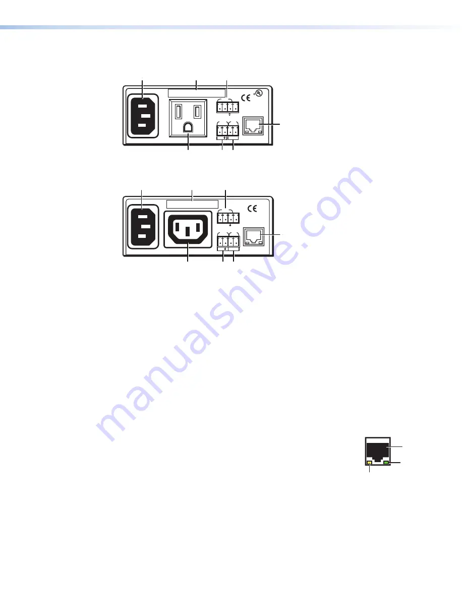
Rear Panels
12A MAX
POWER OUTPUT 12A MAX
LAN
COM
TX
IN
S
G
+5V
RX
INPUT
IR
MAC ADDRESS
100-120VAC 50/60Hz
US
LISTED 17TT
AUDIO/VIDEO
APARATUS
®
A
A
B
B
C
C
D
D
E
E
F
F
G
G
Figure 2.
IPL T PC1 Rear Panel (120 VAC)
10A MAX
POWER OUTPUT 10A MAX
LAN
COM
TX
IN
S
G
+5V
RX
INPUT
IR
MAC ADDRESS
200-240VAC 50/60Hz
A
A
B
B
C
C
D
D
E
E
F
F
G
G
Figure 3.
IPL T PC1i Rear Panel (220 VAC)
A
Power connector
— Connect a power cord from a wall outlet to this male IEC power
receptacle.
B
UID label
— Contains the unique User ID number (MAC address) of the unit (for
example, 00-05-A6-00-00-01).
C
COM port (RS-232)
— Connect the output device serial port to this captive screw
connector to enable bidirectional RS-232 device control. This serial port contains
the following four pins, in order from left to right on the rear panel: transmission (Tx),
receiving (Rx), ground (
_
), and +5 V (to tie hand-shaking lines on the controlled device if
needed).
D
LAN connector and LEDs
— An Ethernet connection can be used on an ongoing
basis to monitor and control the PC1 and the device connected to it (see
on page 8 for instructions on connecting the host
to this port).
•
RJ-45 port
— Plug a patch cable into this RJ-45 female socket, and connect the
other end to a network switch, hub, router, or computer.
•
Link LED
— This green LED lights to indicate a good network
connection.
•
Activity LED
— This yellow LED blinks to indicate network
activity.
E
IR port
— Connect an IR emitter to pins 3 (S, for signal) and 4 (G, for
ground) of this shared captive screw connector to enable infrared remote control of the
output device (see
on page 8 for instructions on connecting
an IR emitter to this port).
The PC1 provides enough current to power one IR emitter up to 4000 feet, or a
maximum of four emitters in parallel up to 100 feet each. To enable IR control, load an
Extron IR driver to the PC1 for the output device, using Global Configurator, the PC1
web pages, or IR Learning.
2
3
LAN
RJ-45
Port
Link
LED
Activity
LED
IPL T PC1 • Installation and Rear Panels
5
Summary of Contents for IP Link IPL T PC1
Page 6: ......
Page 8: ...IPL T PC1 Contents viii ...


