Extron electronics HC 403 EU Setup Manual Download Page 14

14

HC 403 EU, HC 403 MK • Setup Guide (Continued)
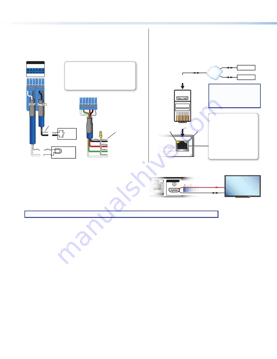
Digital I/O

To use digital input or output to control other devices, provide 
feedback to the receiver, or trigger actions, connect devices to 
the digital I/O ports (

M

) as shown in the following diagram. 

DIGITAL I/O

1 2 G 3 4 G

4

G

3

2

G

1

Digital I/O (digital input/output)

Configure each port as a digital input or output, 

with or w5 VDC pull-up.  Use these ports to:
• Monitor or trigger events and functions (toggle relays, 

issue commands, send e-mail), once configured.

• Trigger LEDs, incandescent lights, or other devices 

that accept a TTL signal.

HCR 102

Rear 

Panel

Switch,

Sensor

(Switches, 

sensors, 

LEDs, 

relays, or 

similar 

items)

Ground

Share the 
same ground 
among I/O 
connections.

Device 4

Device 3

Device 2

Device 1

Wire
Nut

Indicator

LED

LAN

Connect the receiver to a network via the LAN port (

N

for remote monitoring and configuration of the system,  
for touchpanel control, or to allow the receiver to control an 
Ethernet-enabled product. You will need the MAC address 
(

O

) during device discovery and configuration.

2

LAN

-

XX-XX-XX

   E######

22

-

XX-XX-XX

X

  E####

##

#

LAN

Insert Twisted

Pair Wires

Pins:

1

2

3

4

5

6

7

8

HCR 102 Rear Panel

Ethernet

Link
LED

Activity
LED

PC

AV Device

TCP/IP

Network

LAN (Ethernet)

Default protocol:

• IP address: 192.168.254.

250

• Gateway IP address: 0.0.0.0

• Subnet mask: 255.255.255.0

• DNS address: 127.0.0.1

• DHCP: off

• Link speed and duplex level: 

autodetected

• Data rates: 10/100Base-T

Default login credentials:

• Username: 

admin

• Password: 

extron

RJ-45

Connector

HDMI/CEC

Connect an AV device that supports CEC control to the  
HDMI/CEC output port on the receiver (

G

) to allow the HCR 102 

to automatically turn display power on or off based on whether 
an active signal is detected at the selected input.
The HCR 102 sends CEC driver commands to the display for 
basic control functions. CEC control is pre-configured and works “out of the box” but it can be customized further using GC. 

NOTE:

 It can take up to 2 minutes after powering up the receiver to initiate CEC display control.

NOTE:

  Initial units ship with  

the functions of these LEDs  
reversed. Subsequent 
units will ship with 
standard LED functions.

OUTPUTS

L

R

AUDIO

HDMI/CEC

LINK

L

LI

IN

N

NK

K

K

L

L

L

L

L

R

A

A

A

A

A

U

U

UD

D

D

D

D

DIO

O

O

O

HCR 102 Rear Panel

CEC-Compliant Display

HDMI

CEC

MODEL 80

FLAT PANEL

Summary of Contents for HC 403 EU

Page 1: ...wall boxes The HCT 102 MK transmitter has an MK style faceplate and fits most standard two gang MK type wall boxes The HCR 102 receiver is wall furniture or rack mountable The EU and MK transmitter mo...

Page 2: ...DIO OUT LAN PoE VGA OUT HDMI OUT USB 3 POWER 5V 2 3A MAX RESET A PoE B POWER 12V 1 7A MAX HDMI HDMI Tx Rx G RS 232 COM L AUDIO R OUTPUT 1 C T 2 C T 3 C T 4 C T G V CONTACT TALLY LAN INPUT OUTPUT TCP I...

Page 3: ...various product settings to be reset to the factory defaults see Reset Modes a Brief Summary on page 17 I Reset and power LED This green LED indicates either the power status of the transmitter or th...

Page 4: ...put output control ports page 14 N LAN Ethernet connector and LEDs page 14 O MAC address on side of receiver page 14 P Reset button HCT 102 EU MK If the transmitter powers on but is otherwise unrespon...

Page 5: ...s of each HCR 102 see figure 4 O on the previous page or other IP Link Pro device to be used 5 Obtain model names and setup information for devices the HCR 102 will control Step 2 Mount the Receiver P...

Page 6: ...ser or installer must furnish the wall junction box It is not included with the unit Read any installation instructions and safety and regulatory guidelines that come with the wall box before installa...

Page 7: ...word system and control port settings This requires a PC software and a LAN connection To configure network settings from the OSD menu From the Quick Setup menu DHCP Select and enter the DHCP Mode sub...

Page 8: ...cted to the network 4 In Toolbelt use the MAC address to locate the desired device the HCR 102 in the list and select it 5 Use the Set IP feature in Toolbelt or use the Toolbelt Manage Network Setting...

Page 9: ...set the audio input format see table below for the selected input set program audio volume and set audio output format stereo mono Audio Input Format Details None Mutes all audio for selected input Se...

Page 10: ...ts control ports function What to monitor How to control other products When to do things Which touchpanels to interact with Whom to notify how and under what circumstances a Configure the control por...

Page 11: ...R HDCP HDMI VG A AU TO VGA IN HCT 102 EU AUDIO IN AUDIO IN Wall Box Mounting Plate Extron HCT 102 EU 3 Secure the transmitter to the mounting plate as follows a Insert the included screws through the...

Page 12: ...move any excess length Complete details on LockIt installation are available in the LockIt HDMI Cable Lacing Bracket Installation Guide Transmitter Receiver Interconnection Connect the Out port of the...

Page 13: ...orts must be configured using Global Configurator Serial For serial control using RS 232 connect the serial control port of the AV device to the COM port see figure 3 K on page 4 of the HCR 102 receiv...

Page 14: ...n 2 LAN XX XX XX E 2 2 XX XX XX X E LAN Insert Twisted Pair Wires Pins 1 2 3 4 5 6 7 8 HCR 102 Rear Panel Ethernet Link LED Activity LED PC AV Device TCP IP Network LAN Ethernet Default protocol IP ad...

Page 15: ...LAN Tx Rx G RS 232 OVER TP Tx Rx G RS 232 POWER REMOTE 12V A MAX OUT SIG LINK HCT 102 R POWER 12V A MA Ground all devices Return AV and Communication Only 12 VDC input 12 VDC input Ridged Smooth Exte...

Page 16: ...CM 2Ch and Multi Ch These two LEDs E on the receiver indicate the presence or absence of the specific types of audio signal on the selected active input Audio LED Type Audio Input LED State and Indica...

Page 17: ...orted on firmware version 1 01 or higher By default DHCP is off and the unit uses a static IP address When you disable the DHCP client by using this mode the unit reverts to using the previously set s...

Page 18: ...he software file For other software there is a link for contacting an Extron support representative who can provide you access to the latest version To obtain Extron control product software you must...

Reviews: