Extron electronics HC 403 EU Setup Manual Download Page 11

11

Step 9 — Mount the HCT 102 EU or HCT 102 MK

Before mounting the transmitter, make sure that all device cables have been fed through the wall frame and are connected to the 
rear panel.
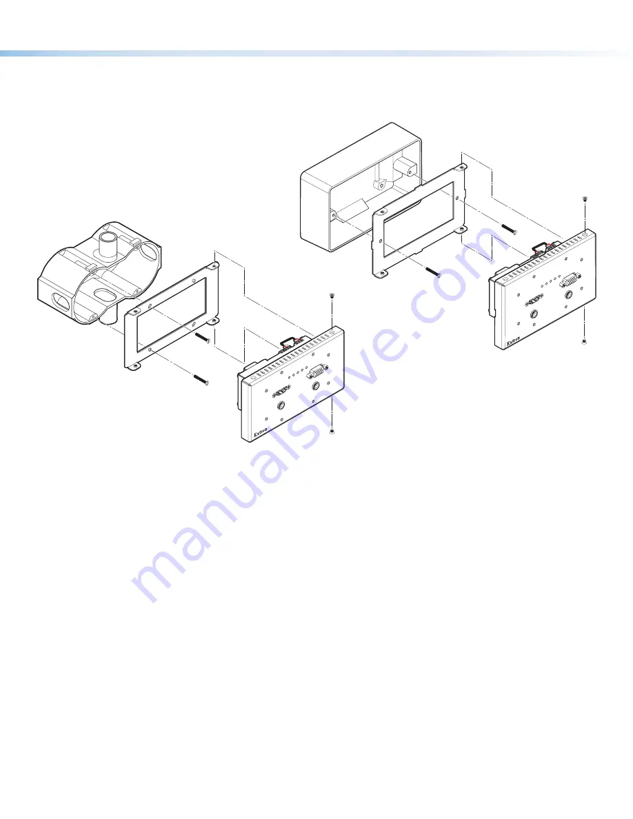
To mount the transmitter (see figures 9 and 10):

1. 

Disconnect power at the source from all devices in the system.

2. 

Align the mounting holes in the transmitter with  
those in the mounting plate. (The mounting plate  
was attached to the wall box in  

Site preparation

 on page 6.)    

HD

MI IN

PW

R

HD

CP

HD

MI

VGA

AU

TO

VG

A IN

HC

T 1

02 

EU

AU

DIO IN

AU

DIO IN

Wall Box

Mounting Plate

Extron

HCT 102 EU

3. 

Secure the transmitter to the mounting plate as follows:

a. 

Insert the included screws through the mounting holes at the top and bottom of the transmitter and into the 
corresponding threaded holes in the mounting plate.

b. 

Using a Phillips screwdriver, lightly tighten the screws until snug.

4. 

Reconnect power to all devices.

Figure 9. 

Mounting the  
HCT 102 EU Transmitter to an EU Wall Box

HD

MI IN

PW

R

HD

CP

HD

MI

VGA

AU

TO

VG

A IN

HCT

 10

2 MK

AU

DIO IN

AU

DIO IN

Wall Box

Mounting Plate

Extron

HCT 102 MK

Figure 10. 

Mounting the HCT 102 D 

Transmitter to an MK Wall Box

Summary of Contents for HC 403 EU

Page 1: ...wall boxes The HCT 102 MK transmitter has an MK style faceplate and fits most standard two gang MK type wall boxes The HCR 102 receiver is wall furniture or rack mountable The EU and MK transmitter mo...

Page 2: ...DIO OUT LAN PoE VGA OUT HDMI OUT USB 3 POWER 5V 2 3A MAX RESET A PoE B POWER 12V 1 7A MAX HDMI HDMI Tx Rx G RS 232 COM L AUDIO R OUTPUT 1 C T 2 C T 3 C T 4 C T G V CONTACT TALLY LAN INPUT OUTPUT TCP I...

Page 3: ...various product settings to be reset to the factory defaults see Reset Modes a Brief Summary on page 17 I Reset and power LED This green LED indicates either the power status of the transmitter or th...

Page 4: ...put output control ports page 14 N LAN Ethernet connector and LEDs page 14 O MAC address on side of receiver page 14 P Reset button HCT 102 EU MK If the transmitter powers on but is otherwise unrespon...

Page 5: ...s of each HCR 102 see figure 4 O on the previous page or other IP Link Pro device to be used 5 Obtain model names and setup information for devices the HCR 102 will control Step 2 Mount the Receiver P...

Page 6: ...ser or installer must furnish the wall junction box It is not included with the unit Read any installation instructions and safety and regulatory guidelines that come with the wall box before installa...

Page 7: ...word system and control port settings This requires a PC software and a LAN connection To configure network settings from the OSD menu From the Quick Setup menu DHCP Select and enter the DHCP Mode sub...

Page 8: ...cted to the network 4 In Toolbelt use the MAC address to locate the desired device the HCR 102 in the list and select it 5 Use the Set IP feature in Toolbelt or use the Toolbelt Manage Network Setting...

Page 9: ...set the audio input format see table below for the selected input set program audio volume and set audio output format stereo mono Audio Input Format Details None Mutes all audio for selected input Se...

Page 10: ...ts control ports function What to monitor How to control other products When to do things Which touchpanels to interact with Whom to notify how and under what circumstances a Configure the control por...

Page 11: ...R HDCP HDMI VG A AU TO VGA IN HCT 102 EU AUDIO IN AUDIO IN Wall Box Mounting Plate Extron HCT 102 EU 3 Secure the transmitter to the mounting plate as follows a Insert the included screws through the...

Page 12: ...move any excess length Complete details on LockIt installation are available in the LockIt HDMI Cable Lacing Bracket Installation Guide Transmitter Receiver Interconnection Connect the Out port of the...

Page 13: ...orts must be configured using Global Configurator Serial For serial control using RS 232 connect the serial control port of the AV device to the COM port see figure 3 K on page 4 of the HCR 102 receiv...

Page 14: ...n 2 LAN XX XX XX E 2 2 XX XX XX X E LAN Insert Twisted Pair Wires Pins 1 2 3 4 5 6 7 8 HCR 102 Rear Panel Ethernet Link LED Activity LED PC AV Device TCP IP Network LAN Ethernet Default protocol IP ad...

Page 15: ...LAN Tx Rx G RS 232 OVER TP Tx Rx G RS 232 POWER REMOTE 12V A MAX OUT SIG LINK HCT 102 R POWER 12V A MA Ground all devices Return AV and Communication Only 12 VDC input 12 VDC input Ridged Smooth Exte...

Page 16: ...CM 2Ch and Multi Ch These two LEDs E on the receiver indicate the presence or absence of the specific types of audio signal on the selected active input Audio LED Type Audio Input LED State and Indica...

Page 17: ...orted on firmware version 1 01 or higher By default DHCP is off and the unit uses a static IP address When you disable the DHCP client by using this mode the unit reverts to using the previously set s...

Page 18: ...he software file For other software there is a link for contacting an Extron support representative who can provide you access to the latest version To obtain Extron control product software you must...

Reviews: