


12
HC 403 EU, HC 403 MK • Setup Guide (Continued)
Cabling
Attach cables using the following wiring diagrams as a guide. Full details are available in the
HC 400 Series User Guide
.
AV Inputs
Analog audio input
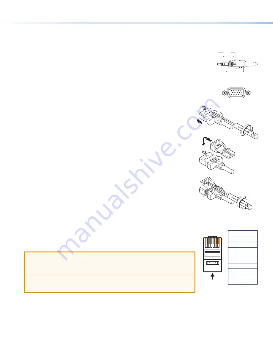
For analog audio sources, connect the source device to the audio input 3.5 mm tip-ring-sleeve (TRS)
connector on the transmitter (see figure 3 and figure 4,
B
on page 4 for connector location). Wire
the connector as shown at right.
Analog video input
Connect an analog RGB video input source to the 15-pin HD RGB input connector (
C
) on the transmitter.
Digital AV input
For HDMI video and for digital audio embedded within HDMI signals:
1.
Connect a digital video source device to any HDMI input connector on the
transmitter or receiver (see
D
in
Rear, Side, and Front Panel Features
on
page 4).
2.
To secure each cable to the unit, attach an Extron LockIt
®
bracket to the unit and
secure it to the cable with a zip tie.
a.
Plug the HDMI cable into the panel connection (see
a
at right).
b.
Loosen the HDMI connection mounting screw from the panel enough to allow the
LockIt lacing bracket to be placed over it (
b
). The screw does not have to be
removed.
c.
Place the LockIt lacing bracket on the screw and against the connector (
c
), then
tighten the screw (
d
) to secure the bracket.
d.
Loosely place the included tie wrap around the connector and the LockIt lacing
bracket as shown (
e
).
e.
While holding the connector securely against the lacing bracket, tighten the tie
wrap, then remove any excess length.
Complete details on LockIt installation are available in the
LockIt HDMI Cable Lacing
Bracket Installation Guide
.
Transmitter-Receiver Interconnection
Connect the Out port of the transmitter (figure 4,
E
, on page 4) to the In port of the receiver
(figure 3,
F
) using a shielded twisted pair CAT
x
cable of up to up to 230 feet (70 m), as shown in
figure 1
on page 2. Terminate the cable with shielded RJ-45 connectors using the
TIA/EIA-T568B wiring standard at both ends, as shown at right.
ATTENTION:
•
Do not connect this port to a computer data network or a telecommunications network.
•
Veuillez ne pas connecter ce port à un réseau de données informatiques ou à un
réseau de télécommunications.
•
Do not use Extron UTP23SF-4 Enhanced Skew-Free AV UTP cable or STP201 cable.
•
N’utilisez pas le câble AV Skew-Free UTP version améliorée UTP23SF-4 d’Extron ou
le câble STP201.
For optimal performance, Extron highly recommends the following:
•
Use the TIA/EIA-T568B wiring standard for terminating all STP cables with RJ-45 connectors.
•
Use shielded twisted pair cable, 24 AWG solid conductor or better, with a minimum cable bandwidth of 400 MHz.
•
Use shielded RJ-45 plugs to terminate the cable.
•
Overall transmission distance capabilities vary depending on the number of patches used. If possible, limit the number of
patches to 2 total.
•
If patches must be used in the system, Extron recommends shielded CAT 6 (or better) patch cables.
Sleeve (Gnd)
Ring (R)
Tip (L)
3.5 mm Stereo Plug
(unbalanced input)
3
a
b
c
d
e
5
Pin
1
2
3
6
7
8
4
Wire color
White-green
Green
White-orange
White-blue
Orange
White-brown
Brown
Blue
TIA/EIA-T568B
Insert twisted
pair wires.
12345678
Pins:


