background image

1

IMPO

RTAN

T:

Go to www

.extron.com f

or the complete 

user guide

, installation instructions,

 and 

specifications bef

ore connecting the 

product to the po

wer sour

ce.

EBP 100 and EBP 200 • Setup Guide

The Extron EBP 100 and EBP 200 eBUS

®

 Button Panels are fully customizable AV system control interfaces for use with Extron 

IPCP Pro Series Control Processors.
Each EBP button panel includes two eBUS ports, which support both power and communications between the IPCP Pro 
control processor and eBUS devices. Up to eight eBUS endpoint devices such as EBP button panels can be connected to 
the control processor and to each other in various cabling topologies. Cabling topology refers to the physical layout of cabling 
interconnections between devices in a network such as an eBUS system. eBUS systems can include daisy chain, star, or hybrid 
system (a combination of both types) topologies (see the 

EBP 100 and EBP 200 User Guide


for basic diagrams). Every endpoint 

device must have a unique identification address (bus ID) within the system.
Setup involves setting bus ID DIP switches on the EBPs, then using Extron Global Configurator

®

 (GC) Plus and Professional 

software, or Global Scripter programming, to configure the control processor. Once configured, the AV system can be controlled 
from any of its EBPs.
This guide provides basic instructions for an experienced installer to install an EBP 100 or EBP 200 button panel. For more details 
on the EBPs, see the 

EBP 100 and EBP 200 User Guide

, available on 

www.extron.com

. For details on configuration, see the 

software help files.
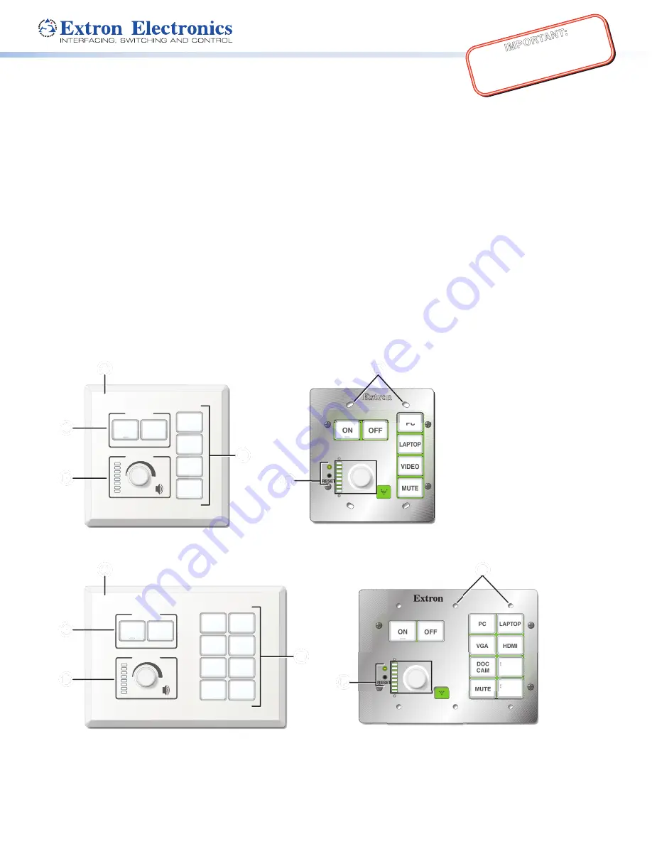
Features

Front Panel Features

Extron

DISPLAY

ON

PC

VIDEO

OFF

LAPTOP

MUTE

VOLUME

Extron

ON

VID

OFF

LAP

MU

VOLUME

PC

E

RESET

E

PC

DOC

CAM

VGA

ON

OFF

MUTE

LAPTOP

HDMI

SCREEN

UP

SCREEN

DOWN

RESET

Extron

DISPLAY

VOLUME

Extron

VOLUME

ON

OFF

PC

DOC

CAM

VGA

MUTE

LAPTOP

HDMI

SCREEN

UP

SCREEN

DOWN

C

C

C

C

D

D

D

D

D

D

D

D

C

C

C

C

B

B

B

B

A

A

A

A

B

B

B

B

A

A

A

A

EBP 100 Front Panel with Faceplate

EBP 100 Front Panel without Faceplate

E

E

E

E

F

F

F

F

F

F

F

F

EBP 200 Front Panel with Faceplate

EBP 200 Front Panel without Faceplate

E

E

E

E

Figure 1. 

Front Panels With and Without Faceplates

A

 Faceplate

B

 Mounting holes  

(EBP 100: x4, EBP 200: x6)

C

 Display power buttons

D

 Volume LEDs and knob

E

 Function buttons

F

 Reset LED and button

Summary of Contents for EBP 100

Page 1: ...tting bus ID DIP switches on the EBPs then using Extron Global Configurator GC Plus and Professional software or Global Scripter programming to configure the control processor Once configured the AV system can be controlled from any of its EBPs This guide provides basic instructions for an experienced installer to install an EBP 100 or EBP 200 button panel For more details on the EBPs see the EBP ...

Page 2: ...e Installation Site ATTENTION Installation and service must be performed by authorized personnel only L installation et l entretien doivent être effectués par le personnel autorisé uniquement Extron recommends installing the EBP into a grounded UL Listed electrical junction box Extron recommande d installer le EBP dans un boîtier d encastrement électrique mis à la terre listé UL If the EBP will be...

Page 3: ...late with the other hand and pulling the faceplate away from the unit 2 Gently separate the button lens button cap from its white diffuser insert the end of the provided Extron removal pry tool into the corner notch and gently twist the tool see 1 in the image at right 3 Remove the label insert from the button cap 4 Select one of the button labels from the printed label sheets included with the un...

Page 4: ...EBP 100 Rear Panel eBUS port on an IPCP Pro or on an EBP or other eBUS endpoint Figure 3 Rear Panel Features Including DIP Switch Location and Settings Each EBP in a system must have a different unique bus ID address a six bit binary number which you set by using the DIP switch assembly on the rear panel of each EBP Switch 1 on the left sets the most significant bit highest number 32 Switch 6 sets...

Page 5: ...rtifiée UL de classe 2 ou LPS et paramétré à 12 VDC et 1 0 A minimum Unless otherwise stated the AC DC adapters are not suitable for use in air handling spaces or in wall cavities Sauf mention contraire les adaptateurs AC DC ne sont pas appropriés pour une utilisation dans les espaces d aération ou dans les cavités murales The installation must always be in accordance with the applicable provision...

Page 6: ...device drivers and link them to each assigned port Configure settings serial protocol relay behavior digital input volume control settings as needed b Set up monitors schedules macros and local variables c Set up the eBUS button panel buttons assign appropriate commands and actions macros timers local variables monitors or feedback to the buttons 2 Save the project 3 Build and upload the system co...

Page 7: ...x wall or surface mounting box or mud ring as follows see 1 in figures 7 and 8 a Insert the included screws through the oval slots at the top and bottom of the EBP through the plastic spacer if not using a mud ring and into the corresponding threaded holes in the box or mud ring b Using a Phillips screwdriver lightly tighten the screws until snug Extron DISPLAY VOLUME 2 2 1 1 EBP 100 Wall Mounting...

Page 8: ... FAX Extron Asia 65 6383 4400 65 6383 4664 FAX Extron Japan 81 3 3511 7655 81 3 3511 7656 FAX Extron China 86 21 3760 1568 86 21 3760 1566 FAX Extron Middle East 971 4 299 1800 971 4 299 1880 FAX Extron Australia 61 8 8351 2188 61 8 8351 2511 FAX Extron India 1800 3070 3777 Inside India Only 91 80 3055 3777 91 80 3055 3737 FAX 2016 Extron Electronics All rights reserved All trademarks mentioned ar...

Reviews: