


Callout
Description
1
Main mounting bracket mounting holes
2
Main mounting bracket feet
2 Insert the Phillips pan head screws into the main mounting bracket holes and attach the bracket to
the wall.
Use screw-in anchors, if needed.
3 Connect the Ethernet cable RJ45 connector into the GE1 port.
4 Place the access point onto the bracket feet and slide it down to lock it in place.
Install a Security Torx Locking Screw
The security torx locking screw is used to prevent the access point from being removed from the main
mounting bracket (#37201). There are two security lock screw holes on the rear of the access point.
Follow this procedure to install the security torx locking screw using one of the security lock holes on
the access point.
Note
Perform this task after the access point is attached to the main mounting bracket on a drywall
or wood wall.
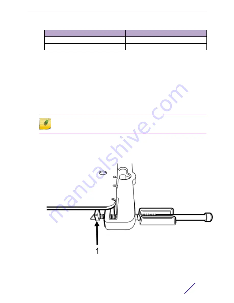
1 Line up the security torx locking screw using the rear guides on the access point.
2 Tighten the security torx locking screw using a T8 bit screwdriver.
3 Turn the locking screw into the security screw hole until the security torx locking screw passes
through to the other side and touches the screw stop feature.
Figure 2: Security torx locking screw stop feature
Install the Access Point
ExtremeMobility™ Access Points AP410i/e
14


