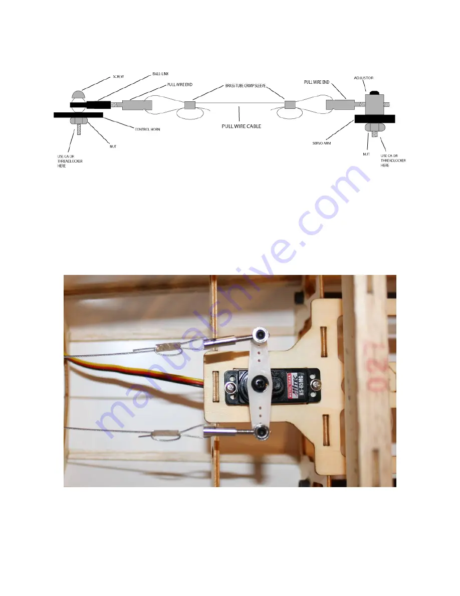
Please examine the rudder pull-pull system assembly diagram closely:
Start by attaching the cables to the pull-wire end at the front, where they will attach to the . Crimp well,
preferably by making creases in the crimp tube with a sharp pliers or cutters, rather than smashing it
completely flat. Apply a drop of thin ca to the completed crimp to prevent it from sliding on the cable.
Insert the pull-wire ends into the servo connectors on the rudder servo as shown, just barely poking
through the servo connectors, and tighten down the set screws with a 1.5mm hex wrench. Note that the
cables cross each other once inside the fuselage, making an “X” shape.
15


