


Chapter 3 – Unpacking & Installation
User Manual
15
Vortex
®
Precedence
Rev 3.6
spindle is removed for any reason the following
procedures describe how to re-align the upper
and lower tools so that they are level and
centered.
Tool Plate Leveling
1.
Attach the leveling and centering
indicator assembly to the spindle. The
leveling and centering indicator
assembly is a tool specifically designed
for use with the Vortex and can be
purchased from Extol.
2.
Position the indicator so that it lightly
touches the lower tool plate.
3.
Press the E-Stop button and manually
rotate the spindle while watching the
indicator for high and low spots.
4.
Loosen the 4 tool plate mounting bolts
(SHCS) and loosen the 4 adjustment
locknuts. The locknuts are located under
the tool plate and lock the leveling bolt
to the machine base.
5.
Adjust each of the 4 leveling bolts so
that there is as little indicator movement
as possible as you rotate the indicator
around the lower tool plate.
6.
Tighten the 4 locknuts and rotate the
indicator around again to verify that the
plate is level. If it is not level, loosen the
locknuts re-adjust the leveling bolt and
re-tighten one bolt at a time until the
lower tool plate is level.
Tool Plate Centering
1.
First complete the tool plate leveling
procedure as outlined above.
2.
Move the indicator so that it touches the
inside of the hole in the lower tool plate
that is directly below the spindle.
3.
Now rotate the spindle while watching
the indicator.
4.
Adjust the lower tool plate so that there
is as little indicator movement as
possible as you rotate it.
5.
Tighten down the 4 tool plate mounting
bolts (SHCS).
6.
Rotate the indicator around again and
verify that the plate is centered. If it is
not, loosen the bolts and repeat.
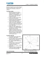
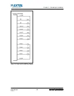
Lower Tool Mounting
Figure 3-1 Lower Tooling Plate Bolt Pattern
Summary of Contents for VORTEX PRECEDENCE G1
Page 66: ...Chapter 6 Operation User Manual 60 Vortex Precedence Rev 3 6 Sequence of Operations Flowchart ...
Page 69: ...Chapter 6 Operation User Manual 63 Vortex Precedence Rev 3 6 ...
Page 88: ...Chapter 8 Troubleshooting User Manual 82 Vortex Precedence Rev 3 6 Servo Drive Alarms ...
Page 89: ...Chapter 8 Troubleshooting User Manual 83 Vortex Precedence Rev 3 6 ...
Page 90: ...Chapter 8 Troubleshooting User Manual 84 Vortex Precedence Rev 3 6 ...
Page 91: ...Chapter 8 Troubleshooting User Manual 85 Vortex Precedence Rev 3 6 Servo Drive Warnings ...
Page 104: ...651 Case Karsten Drive Zeeland MI 49464 1 800 324 6205 www extolinc com ...


