background image

17


EX

-

42034


English


RS

-

485 2

-

wire mode


RS

-

422 and RS

-

485 4

-

wire mode


Termination for RS

-

422, RS

-

485 2

-

wire and RS

-

485 4

-

wire mode:


© Copyright 2020 by EXSYS Vertriebs GmbH. All Rights Reserved


4.2


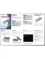
Jumper Settings


JP1:


P12V


X12V


P5V


X5V


If you have the jumper JP2

-

JP5 set to 5V or 12V, you can adjust the 

voltage with the jumper JP1. There are 4 different power sources. 


(

Attention!

 Connector J4 must be connected to the power supply!)


X5V


=


5Volt from PC Power Supply (Factory Setting)


P5V


=


5Volt from Mainboard


X12V


=


12Volt from PC Power Supply


P12V


=


12Volt from Mainboard


5V


=


At pin 9 is now a voltage of +5V DC.  


    (Factory Setting) 


12V


= At pin 9 is now a voltage of +12V DC.


There are 4 jumper on the board, so you can make the settings individu-

ally  for  all  serial  ports.  The  voltage  adjustment  can  be  made  with  the 

jumper JP1. But this should not be adjusted for standard applications.


JP2

-

JP5:


12V 5V


4. Switch and Jumper Settings


4.1


Switch Settings


Summary of Contents for EX-42034

Page 1: ...Vers 1 0 08 01 20 RS 232 422 485 PCI Card with 4 x 9 Pin Connector EX 42034 RS 232 422 485 PCI Karte mit 4 x 9 Pin Anschluss Manual Anleitung...

Page 2: ...lation 9 6 Treiber Installation 9 11 7 Technische Daten 11 1 Description 12 2 Extent of Delivery 12 3 Layout and Connections 13 14 3 1 Layout 13 3 2 Connections 13 14 4 Switch and Jumper Settings 14 1...

Page 3: ...arte vom System BIOS und beim installieren des Betriebssystems automatisch vorgenommen werden ber die Jumper k nnen Sie 5V oder 12V auf Pin 9 des seriellen Anschluss umleiten Achten Sie bitte darauf d...

Page 4: ...DB9 EX 42034 DB9 Endger t 1 DCD 1 DCD 2 RXD 2 RXD 3 TXD 3 TXD 4 DTR 4 DTR 5 GND 5 GND 6 DSR 6 DSR 7 RTS 7 RTS 8 CTS 8 CTS DB9 EX 42034 DB9 Endger t 1 TXD 1 TCD 2 TXD 2 TXD 3 RXD 3 RXD 4 RXD 4 RXD 5 G...

Page 5: ...or Switches entnehmen Zus tzlich sind auf der R ckseite der Platine die Einstellm glichkeiten des Mode und Terminator Switche auf gedruckt Copyright 2020 by EXSYS Vertriebs GmbH All Rights Reserved 3...

Page 6: ...RS 232 RS 422 RS 485 2 Draht RS 485 4 Draht Port 1 Port 2 Port 3 Port 4 Mode Terminator Switch S1 S4_Mode 4 Switch und Jumper Einstellungen 4 1 Switch Einstellungen Copyright 2020 by EXSYS Vertriebs...

Page 7: ...S4_Mode Resistoren f r RS 422 RS 485 2 Draht und RS 485 4 Draht Mode 4 Switch und Jumper Einstellungen 4 1 Switch Einstellungen Resistoren Off Resistoren On Terminator Off Terminator On Copyright 2020...

Page 8: ...5V Am Pin 9 liegt jetzt eine Spannung von 5V DC an Werkseinstellung 12V Am Pin 9 liegt jetzt eine Spannung von 12V DC an Es gibt den Jumper vier Mal auf der Platine sodass Sie f r alle seriellen Port...

Page 9: ...e einzustecken 5 Installieren Sie als erstes die beiden 2x 9 Pin B gel an den internen seriellen 10 Pin Header S3 S4 6 Installieren Sie nun die externe Stromversorgung zur Entlastung des Mainboards un...

Page 10: ...de Treiber f r die Server Betriebssysteme installiert Windows Server 2003 XP Treiber Windows Server 2008 VISTA Treiber Windows Server 2008R2 Windows 7 Treiber Windows Server 2012 Windows 8 x Treiber W...

Page 11: ...x 120 00 mm Gewicht 200g Copyright 2020 by EXSYS Vertriebs GmbH All Rights Reserved 6 Treiber Installation Linux Mac OS Die Treiber f r Linux Mac OS Systeme befinden sich ebenfalls im Ordner USB_to_IO...

Page 12: ...ess or IRQ settings manually they will be obtained automatically by the system BIOS and operating system With the jumpers you can enable 5V or 12V power to pin 9 Please note if you use power to pin 9...

Page 13: ...for the Power Source Power Supply or PCI Bus J4 Connector for Power Supply S1 S2 9 Pin Male Serial Connector S3 S4 Internal Serial 10 Pin Header for Port 3 4 3 2 Connections DB9 EX 42034 DB9 Device 1...

Page 14: ...modes RS 232 RS 422 RS 485 2 wire or RS 485 4 wire and for the signal termination for RX RX TX and TX see picture on page 15 The settings can be set individually for each serial port The DIP switch a...

Page 15: ...Copyright 2020 by EXSYS Vertriebs GmbH All Rights Reserved Modes RS 232 RS 422 RS 485 2 wire RS 485 4 wire Port 1 Port 2 Port 3 Port 4 Mode Terminator Switch S1 S4_Mode 4 Switch and Jumper Settings 4...

Page 16: ...er Settings 4 1 Switch Settings Mode Terminator Switch S1 S4_Mode Resistors for RS 422 RS 485 2 wire and RS 485 4 wire mode Resistor Off Resistor On Terminator Off Terminator On Copyright 2020 by EXSY...
Page 17: ...Attention Connector J4 must be connected to the power supply X5V 5Volt from PC Power Supply Factory Setting P5V 5Volt from Mainboard X12V 12Volt from PC Power Supply P12V 12Volt from Mainboard 5V At...

Page 18: ...rd by force 5 First install the two 2x 9 pin brackets to the internal serial 10 pin headers S3 S4 6 Now install the external power supply to relieve the mainboard and with the power source selected if...

Page 19: ...ver for the following Windows Server Version Windows Server 2003 XP Driver Windows Server 2008 VISTA Driver Windows Server 2008R2 Windows 7 Driver Windows Server 2012 Windows 8 x Driver Windows Server...

Page 20: ...it Rel Humidity 5 to 95 Power 5V or 12V via PCI Slot or SATA Power Connector Size 132 30 x 120 00 mm Weight 200g 6 Driver Installation Linux Mac OS The drivers for Linux Mac OS systems are also in the...

Reviews: