- 31 -
FIGURE 10
PARKING BRAKE NEUTRAL LOCKOUT ADJUSTMENT
6.2.9
Parking brake switch adjustment
a)
Stop engine, wait for all moving parts to stop, and remove key.
b)
Engage parking brake. Adjust the parking brake switch mounting bracket until
jack-shaft engagement arm depresses brake safety switch by at least 1/4”.
c)
Check safety interlock system as outlined in 6.1.5.
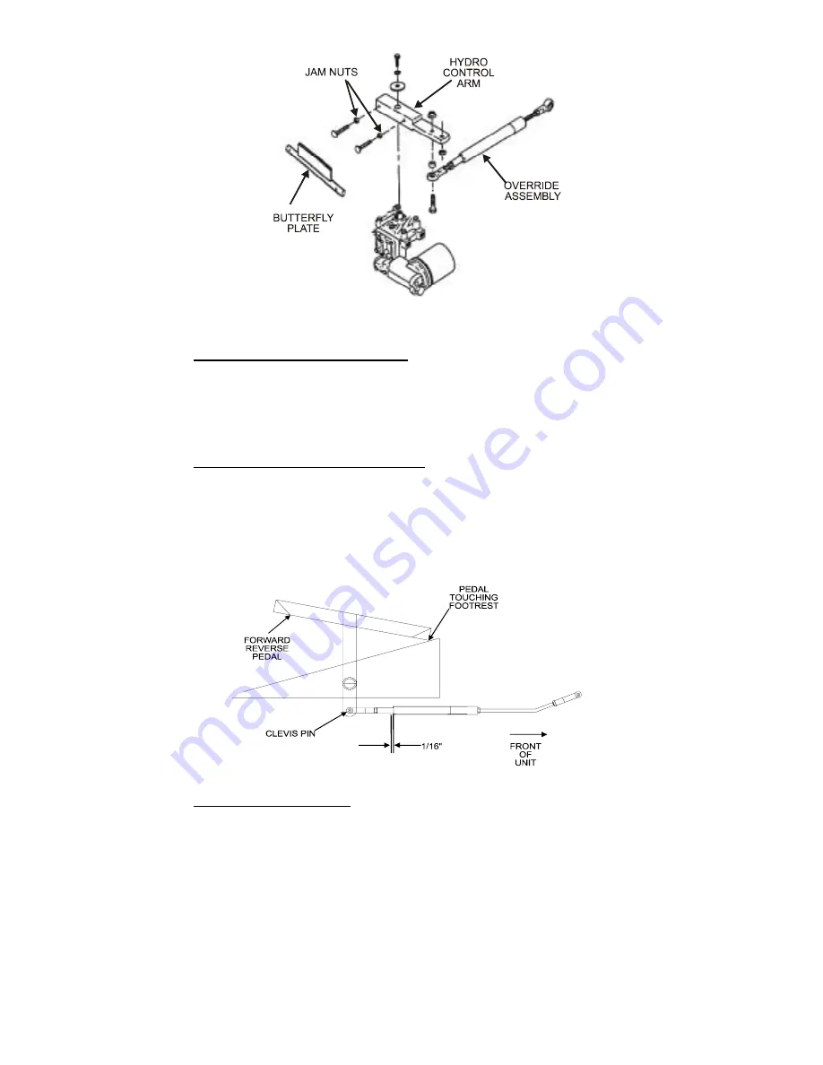
6.2.10 Motion Control Linkage Adjustment
a)
Step down on the forward pedal until it touches the footrest.
b)
Check the gap between the motion override tube and the spacer. This gap
should measure 1/16” (See Figure 11).
c)
If adjustment is required, remove clevis pin at foot pedal end and turn yoke
in or out as required to obtain the 1/16" gap.
FIGURE 11
MOTION CONTROL LINKAGE ADJUSTMENT
6.2.11 Seat Switch Adjustment
a)
Stop engine, wait for all moving parts to stop, and remove key.
b)
With operator out of seat, adjust the seat switch to provide a 1/16”
clearance between the switch plunger and the seat frame (See Figure 12).
c)
To adjust, loosen the top nut securing the seat switch to the seat rail
weldment. Adjust the bottom nut until the 1/16” between plunger and seat
frame has been obtained. Tighten the top nut. Recheck the measurement
and adjust again if necessary.
d)
Check safety interlock system as outlined in 6.1.5.
Summary of Contents for Turf ranger
Page 1: ......
Page 43: ... 38 ...


