background image


14 


ASSEMBLY


MUST


TIGHTEN


IN


SEQUENCE:


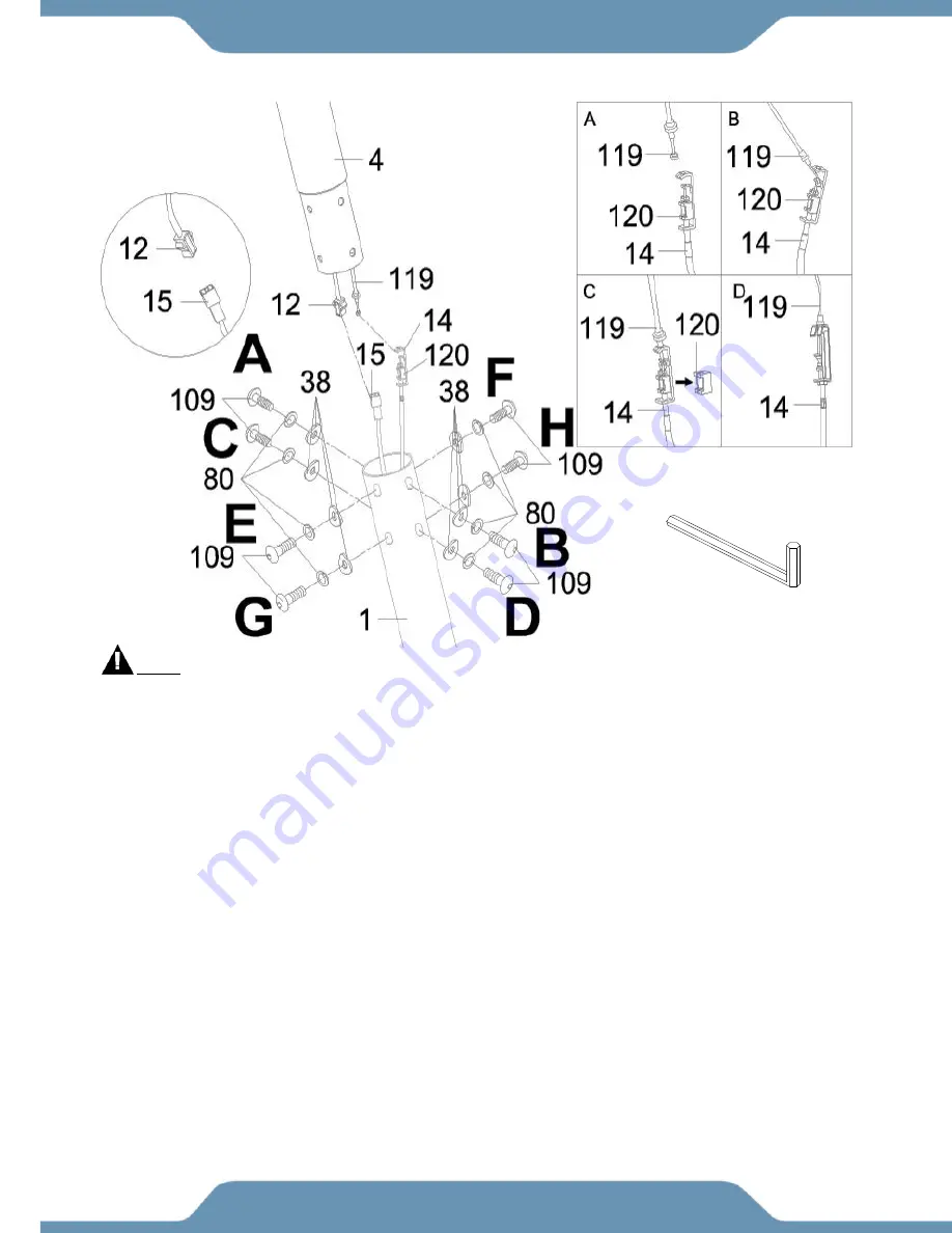
A,B,C,D,E,F,G,H.


Step 4


Assembly of Front Post.


Use the 

5mm Allen Wrench

 to remove eight 

Hexagon Socket Head Bolts (109)

, eight 

Spring 

Washers (80)

, and eight 

Curve Washers (38)

 from the 

Front Post (4)

. Put these hardware aside. 

 
Thread the 

Tension Control Knob Cable (116) 

cable coming out from under 

Main Post (4)

 into 

the cable lock end of the 

Tension Cable (14)

. See 

Figure A

. Once the 

Tension Control Knob 

Cable (116) 

is in place, give it a good tug upwards into the slot of the metal bracket of the 

Tension 

Cable (14)

. See 

Figure B

 . Remove the 

Clip (120)

 from the cable lock end of the 

Tension Cable 

(14)

Figure


C

. If threaded correctly, the connection should look like 

Figure D

.  

 
Connect the 

Console Extension Wire (12)

 from the 

Front Post (4)

 with the 

Extension Sensor 

Wire (15)

 from the 

Main Frame (1)

 
Insert the 

Front Post (4)

 into the 

Main Frame (1)

. Reinstall the previously removed hardware: eight 

Hexagon Socket Head Bolts (109)

, eight 

Spring Washers (80)

, and eight 

Curve Washers (38)


and securely tighten the bolts using the 

5mm Allen Wrench

 provided.


5mm Allen Wrench 

1PC 

Tool: 

Summary of Contents for 1317.5-101016

Page 1: ...instructions carefully before using this product Retail this owner s manual for future reference The specifications of this product may vary from this photo subject to change without notice 1317 5 10...

Page 2: ......

Page 3: ...ABEL PLACEMENTS 3 IMPORTANT SAFETY GUIDELINES 4 OVERVIEW DRAWING 5 PARTS LIST 6 HARDWARE TOOLS PACK 9 ASSEMBLY 12 COMPUTER CONSOLE 24 LEVEL ADJUSTMENTS TRANSPORT 26 TROUBLE SHOOTING MAINTENANCE 27 WAR...

Page 4: ...ays Emailing us with the information above will be the best method to receive a response during peak business hours Website www paradigmhw com Toll Free 1 844 641 7921 Response time may vary via calli...

Page 5: ...3...

Page 6: ...4 LABEL PLACEMENTS...

Page 7: ...ce or adjustments that are instructed in this manual Should any problems arise discontinue usage of the equipment and consult with our customer service 8 Only one person should be on the equipment at...

Page 8: ...6 OVERVIEW DRAWING 1 1 6 1 1 6 1 3...

Page 9: ...k 2 35 Cap Nut M8 4 12 Console Extension Wire L 1050mm 1 36 Washer 8x 16x1 5T 8 13 Console Connection Wire 1 37 Belt Pulley Shaft 12x90mm 2 15 Tension Cable 1 38 Curve Washer 21x 8x2t 14 16 Extension...

Page 10: ...2 63 Self Tapping Screw M5x15mm 5 88B Upper Crank Cover B 2 64 Washer 19 5x 25x2 0T 2 89 Wire Plug 1 65 Nut M10 2 90 Magnet 1 66 Inner C Ring 19 1 91 Spring 0 8x13 1 67 Washer 19 5x 25x3 0T 2 92 Sens...

Page 11: ...lon Locknut M6 1 108 U Shape Plate 1 118 Spring Washer 10mm 1 109 Hexagon Socket Head Bolt M8x15mm 8 119 Tension Control Knob 1 110 Bolt M8 10mm 3 120 Plastic Buckle 1 111 Wave Washer 21 27 0 3 1 121...

Page 12: ...10 HARDWARE TOOLS PACK...

Page 13: ...arallel to the ground Insert two Carriage Bolts 34 through the stabilizer and the front curved bracket and secure the bolts using two Washers 36 two Spring Washers 80 and two Cap Nuts 35 Use the Multi...

Page 14: ...h the stabilizer and the front curved bracket and secure the bolts using two Washers 36 two Spring Washers 80 and two Cap Nuts 35 Use the Multi Hex Tool with Phillips Screwdriver provided to tighten t...

Page 15: ...ck of the Console 102 Refer to Fig AA 2 Mount the Console 102 to the plate on the top of the Front Post 4 while the carefully tucking in the loose wiring Be sure to pull out the Hand Pulse Sensor Wire...

Page 16: ...is in place give it a good tug upwards into the slot of the metal bracket of the Tension Cable 14 See Figure B Remove the Clip 120 from the cable lock end of the Tension Cable 14 Figure C If threaded...

Page 17: ...s 80 and two Curved Washers 38 Tighten the bolts using the 5mm Allen Wrench until they are firm and secure There will be another set of Hand Pulse Sensor Wires 17 coming out from the Handlebar 5 Conne...

Page 18: ...Head Bolts 39 two Curve Washers 38 and two Nylon Locknuts 40 Simultaneously tighten the bolt and nut using both the 5mm Allen Wrench and Multi Hex Tool with Phillips Screwdriver Repeat the steps abov...

Page 19: ...n one Screw Side Cover 114 to where the bushing of the Upper Left Handrail 6L are while inserting one Hexagon Socket Head Bolt 53 one Spring Washer 80 and one Washer 18 into the left side axis of Fron...

Page 20: ...ith the Multi Hex Tool with Phillips Screwdriver provided Repeat the same assembly steps to install the Right Foot Pedal 22R onto the Right Foot Bar 9R Note There are four holes on the Left Foot Bar 9...

Page 21: ...e left Crank 10 Attach the Pedal Cover A 23A to Pedal Cover B 23B with two Round Head Self Tapping Screws 59 Then tighten the hardware with the Multi Hex Tool with Phillips Screwdriver until they are...

Page 22: ...ft side Crank 10 Insert one Hexagon Socket Head Bolt 53 one Wave Washer 70 and one Washer 71 Tighten the bolt using the 5mm Allen Wrench until it is firm and secure Repeat the same assemble steps for...

Page 23: ...Head Bolt 41 two Washers 42 and one Nylon Locknut 44 Simultaneously tighten the bolt and nut with both the 5mm Allen Wrench and Multi Hex Tool with Phillips Screwdriver until they are firm and secure...

Page 24: ...Bars 9R and enclose the U Shape Brackets 8 of the foot bars by sandwiching the U Shape Bracket Covers A 97A over it Secure all the U Shaped Bracket Covers A 97A and Covers B 97B with four Round Head S...

Page 25: ...spective Handrail Arms 7L 7R with both the Foot Bar Covers A 75A Covers B 75B Enclose the axis brackets with the covers using two Round Head Self Tapping Screws 59 by using the Multi Hex Tool with Phi...

Page 26: ...ips Screwdriver to remove two Bolts 33 on the Front Post 4 Attach the Bottle Holder 101 onto the Front Post 4 and tighten them with two Bolts 33 that were previously removed using the same Multi Hex T...

Page 27: ...each function of computer Press and hold the button for 3 seconds all data values will clear to zero except the ODO ODOMETER data values CONSOLE FUNCTIONS SCAN Press the button until the screen displa...

Page 28: ...nsors with both your hands during exercise To ensure the pulse readout is more precise please always hold on to the handlebar grip sensors with two hands instead of just with one hand only when you tr...

Page 29: ...s on the Rear Stabilizer 3 as needed to level the elliptical Transporting the Elliptical Hold the Handlebar 5 and pull the machine until the wheels on the Front Stabilizer 2 make contact with the floo...

Page 30: ...SOLUTION Avoid gripping the hand pulse sensors too tight Try to maintain moderate pressure while holding onto the hand pulse sensors PROBLEM The elliptical makes a squeaking noise when in use SOLUTION...

Page 31: ...s 4 Damage caused by normal wear and tear vandalism accidental or by animals 5 Any act of Nature such as fire flooding snow ice hurricane earthquake lightning or other natural disaster environmental c...

Page 32: ...___________________ TELEPHONE Day _____________________________________________ Night ____________________________________________ SERIAL _____________________________________________________ MODEL __...

Reviews: