background image

3.

Release tension on the blade by flipping the blade tension lever forward.

4.

Loosen the thumbscrew on the lower blade mount, located under the table, to release the blade from the mount.

5.

Raise the upper arm assembly which will lift the blade up through the hole and above the table.

6.

Position the workpiece on the table so that the guide hole lines up with the hole in the table.

7.

Lower the arm assembly with one hand while guiding the blade through the hole in the workpiece and table.

8.

Re-install the bottom end of the blade in the lower blade mount and tighten the thumbscrew, only 
enough to secure the blade in the lower blade clamp and prevent it from slipping.

Note: Overtightening the blade clamp thumbscrews can  cause premature wear to the blades gripping surface and result
in blade slippage or cause premature wear of the threads in the blade clamp housing. (added this sincd Norm’s copy)

9.

Flip back the blade tension lever to re-tension the blade and test the blade tension as described in 
“Installing or Changing Blades” section of this manual.

10.

To begin cutting follow the same steps as described in “Basic 90° straight or curved cuts” section on page 13 of 
this manual.

TO REDUCE THE RISK OF INJURY, ALWAYS TURN OFF THE SAW AND WAIT FOR THE BLADE TO COME TO
A COMPLETE STOP BEFORE REACHING IN TO REMOVE WASTE MATERIAL FROM A FRET CUT.

ANGLE OR BEVEL CUTTING

One of the unique features of the EX-16 Scroll Saw is the ability
to tilt the head of the saw in order to make angle or bevel cuts.

The table and the workpiece always stay horizontal (parallel to
the floor) while the blade tilts, keeping your hands in the same
comfortable cutting position as they would normally be for
regular right angle cuts.

Because you are not fighting gravity or working with your
hands or wrists bent in awkward positions, it can be a huge
advantage and makes it easier and safer to make accurate
bevel cuts.

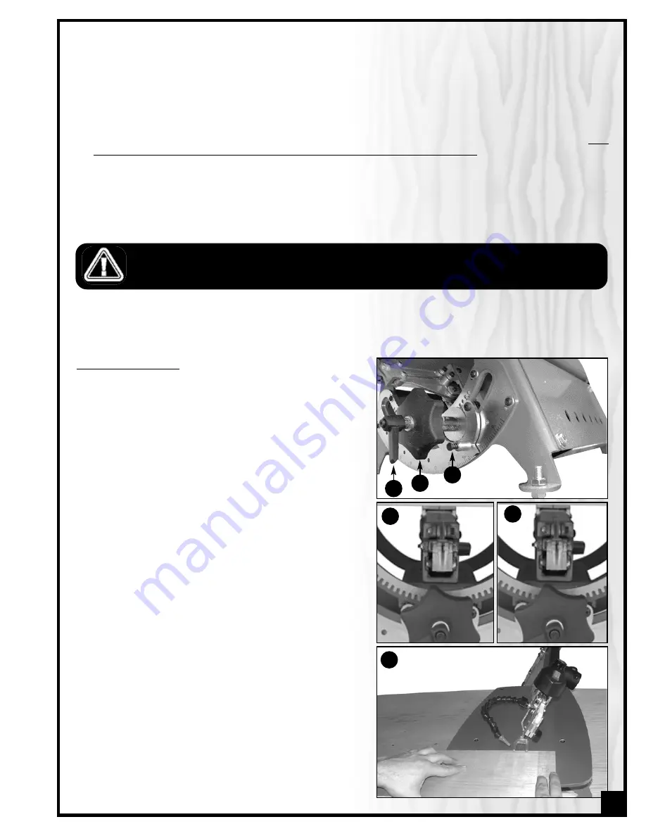
The blade tilt controls are located under the table at the front
saw. To tilt the blade for bevel cutting:

1.

Release the locking lever 

by turning counter-clockwise.

2.

Turn the tilting handle 

left or right to set the blade to the 

desired angle.

Note: Push in and hold the spring loaded indexing pin C to locate

the following common angles: 90º, 45º, 30º & 22.5º both left and

right.

When tilting the blade to the left at extreme angles, it may be
necessary to remove and reverse the lower blade mount thumb-
screw assembly in order to maximize clearance under the table.
(

D

shows the lower blade mount in default position and 

E

shows

it reversed).

3.

Tighten the locking lever 

A

to secure the blade at the 

desired angle.

4.

To begin cutting, follow the same steps as described in 
“Basic 90° straight or curved cuts” section on page 13 of 
this manual. Letter 

F

shows the scroll saw in position for 

bevel cutting.

B

C

A

D

E

F

15

Summary of Contents for EX-16

Page 1: ...surface Quick blade changes with finger operat ed blade clamps no tools required Easy access speed and tension controls Onboard dust blower LENGTH 27 686 mm WIDTH 15 380 mm HEIGHT 17 432 mm BLADE TILT...

Page 2: ...manual handy for future reference Disclaimer The information and specifications in this manual pertain to the unit as it was supplied from the factory at the time of printing Because we are commit ted...

Page 3: ...er our Standard 2 year Limited Warranty or under our Limited Lifetime Warranty all defective parts components or machinery must be returned freight or postage prepaid to General International or to a...

Page 4: ...the optinal stand 10 Mounting to a work surface 10 Choosing Installing a Saw Blade 10 Blade selection 10 Installing or changing blades 11 Operating Instructions 12 On Off switch 12 Adjusting the blad...

Page 5: ...ich it was designed Do not use for purposes not intended 12 Avoid working from awkward or off balance posi tions Do not overreach while cutting keep both feet on floor Never lean over or reach behind...

Page 6: ...ng the saw 17 Never overfeed or force work into the blade 18 Check for alignment and binding of all moving parts broken parts mounting and any other con ditions that may affect the saw s operation 19...

Page 7: ...EXTENSION CORDS THAT HAVE 3 PRONG GROUNDING PLUGS AND 3 POLE RECEPTACLES THAT ACCEPT THE TOOLS PLUG REPAIR OR REPLACE A DAMAGED OR WORN POWER CORD OR PLUG IMMEDIATELY If you find it necessary to use...

Page 8: ...NOB C ON OFF SWITCH D BLADE TENSION LEVER E BLADE CLAMP F BLADE G WORKPIECE HOLD DOWN H TABLE I BLADE TILT LOCKING LEVER J TILT HANDLE K ANGLE INDICATOR L ANGLE ADJUSTMENT SCALE M MOUNTING HOLES 4 N B...

Page 9: ...POWER CORD IS UNPLUGGED DO NOT PLUG IN OR TURN ON THE SCROLL SAW UNTIL YOU HAVE COMPLETED THE ASSEM BLY AND INSTALLATION STEPS DESCRIBED IN THIS SECTION OF THE MANUAL NOTE Unscrew the 4 shipping bolt...

Page 10: ...de selection is dependent on the type and thickness of the material being cut but is also a matter of experi ence and personal preference There are numerous types of blades available on the market spe...

Page 11: ...range of sizes and provide a good combination of fast cutting action with good chip clearance and a relatively smooth finish SKIP TOOTH REVERSE TOOTH BLADE WIDTH THICKNESS TEETH INCH Same appli cation...

Page 12: ...er If the blade is tight and tensioned correctly you will get a clear and even note If so you are ready to proceed to operating and cutting with the saw This saw has an adjustment knob in the rear tha...

Page 13: ...LOWER The workpiece hold down B can be adjusted to assist in preventing the blade from lifting the workpiece up from the table during the cut Loosen the thumbscrew C to set the height to your convenie...

Page 14: ...essentially using this guide hole as the starting point to cut out the piece from within A typical example of fret cutting would be removing the center portion of lettering A The EX 16 is a great tool...

Page 15: ...IN TO REMOVE WASTE MATERIAL FROM A FRET CUT ANGLE OR BEVEL CUTTING One of the unique features of the EX 16 Scroll Saw is the ability to tilt the head of the saw in order to make angle or bevel cuts Th...

Page 16: ...ience frequent blade slippage it may be a sign that it is time to replace the blade clamp thumbscrew B and or the set screws opposite the thumbscrews C Note Overtightening to compensate for blade slip...

Page 17: ...alignment with the table Periodically check the blade for square with the table When needed adjust as described in the following steps to re align the blade square to the table 1 Turn off and unplug...

Page 18: ...5 6 12 23 22 21 20 19 18 25 24 26 27 4 70 28 29 78 52 54 51 51 52 53 23 45 56 23 48 47 45 45 46 41 40 50 49 35 33 34 81 39 38 37 30 31 71 80 58 59 60 61 62 63 64 65 66 67 68 69 70 70 70 72 55 77 EX 16...

Page 19: ...STRAIN RELIEF 1 EX21 A40 GEAR COVER 1 EX21 A41 NUT 3 8XT5 5 1 EX21 A45 ALLEN SCREW 10 32X2 1 4 4 EX21 A46 SCREW 3 8X5 8 1 EX21 A47 WASHER 8 1 EX21 A48 SCREW 8 32X1 4 1 EX21 A49 MOTOR LABEL 1 EX21 A50...

Page 20: ...19 6 7 9 8 29 42 29 43 19 19 19 35 10 12 11 15 11 17 18 14 13 15 11 16 18 3 1 41 44 4 1 19 19 17 16 21 45 17 18 14 21 20 13 26 27 28 37 22 23 24 25 38 39 40 41 43 43 43 44 44 44 EX 16 B 20...

Page 21: ...ER 2 EX21 B17 SCREW 10 32X5 16 8 EX21 B18 WASHER 10X12X1 8 EX21 B19 NUT 1 4 20UNC 12 EX21 B20 ANGLE INDICATOR 1 EX21 B21 ALLEN SCREW 1 4 20X1 2 EX21 B22 E RING ETW 3 1 EX21 B23 TILT DETENT BARREL 1 EX...

Page 22: ...12 28 17 27 17 18 30 31 32 24 23 18 17 35 18 17 39 35 28 12 18 17 33 37 23 38 36 31 23 24 32 17 18 27 30 17 40 57 61 64 2 3 5 7 4 5 6 8 8 9 10 12 59 11 28 28 23 38 37 33 41 42 43 44 45 46 24 23 54N 4...

Page 23: ...0 6 7 EX21 C29N INNER BEARINGR SLEEVE FRONT ROCKER 8 03 X 18 40MM 2 EX21 C30 BEARING INNER SLEEVE LONG 2 EX21 C31 ROCKER MOUNT 2 EX21 C32 CAP SCREW M4X40 2 EX21 C33 CAP SCREW M4X22 6 EX21 C35 STRUT 2...

Page 24: ...rial number of the machine and part number Also a brief description of each item and quantity desired 8360 Champ d Eau Montreal Quebec Canada H1P 1Y3 Tel 514 326 1161 Fax 514 326 5565 Parts Service Fa...

Reviews: