background image

5

9.

Do not connect tool 

to pressure which

potentially exceeds 200 PSI (13.7 BAR).

10. All air line components (hoses,
connectors, filters, regulators, etc.) 

must

be rated for a maximum working pressure
of at least 150 PSI (10.3 BAR) or 150% of
the maximum system pressure, which ever
is greater.

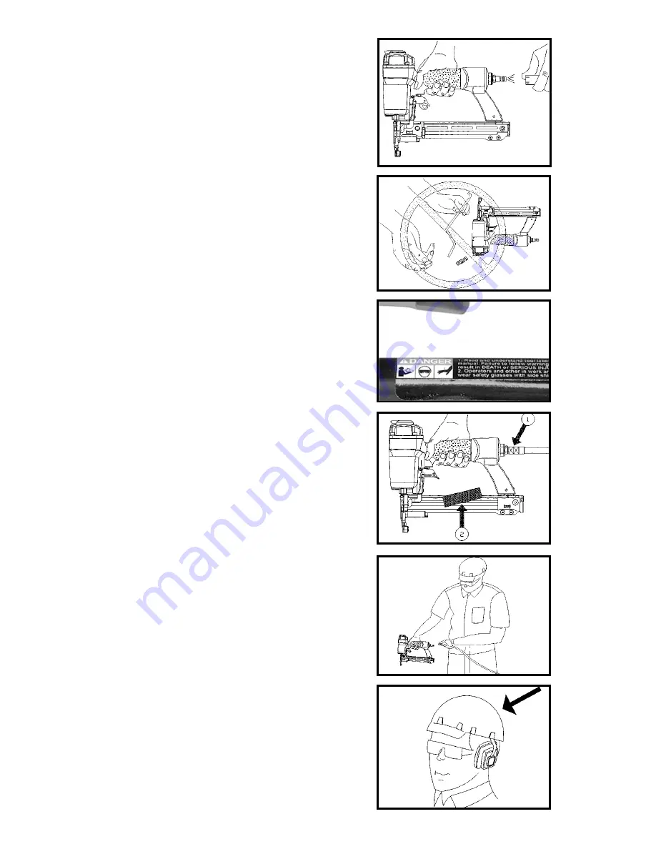
11. Connect tool to air supply hose

with a

coupling that automatically removes all
pressure from the tool when the coupling is
disconnected. Fig. 7.

12. Disconnect tool from air supply hose

before doing tool maintenance, clearing a
jammed fastener, leaving work area, moving
tool to another location, or handing the tool
to another person. Fig. 7.

13. Never use a tool

that is leaking air, has

missing or damaged parts, or requires
repair. Make sure all screws and caps are
securely tightened. Fig. 8.

14. Never use tool if safety, trigger or
springs 

are inoperable, missing or

damaged. Do not alter or remove safety,
trigger, or springs. Make daily inspections
for free movement of trigger and safety
mechanism. Fig. 8.

15. Do not use tool without safety
warning label.

If label is missing, damaged

or unreadable, contact the Customer Care
Department at 1-800-888-2468 for a
replacement. Fig. 9.

16. Only use parts and accessories

approved by DeVilbiss Air Power Company.

17. Connect tool to air supply before

loading fasteners, to prevent a fastener
from being fired during connection. The tool
driving mechanism may cycle when tool is
connected to the air supply. Fig. 10.

18. Always assume the tool contains
fasteners.

No horseplay. Respect the tool

as a working implement. Fig. 11.

19. Operator and bystanders should wear
hard hats

to safeguard against possible

injuries. Fig. 12.

20. Keep bystanders and children away
from work area 

when operating this power

tool. 

Fig. 8

Fig. 9

Fig. 11

Fig. 12

Fig. 7

Fig. 10

Summary of Contents for Ex-Cell A05983

Page 1: ...Power Company Part No A05983 07 22 04 Owners Manual for models ENS100 ENS150 Staplers Record All Information and attach sales receipt here for future reference Purchase Date _________________________...

Page 2: ...bre d ordre TABLE OF CONTENTS SAFETY GUIDELINES AND INSTRUCTIONS 3 GENERAL SAFETY RULES 4 6 FUNCTIONAL DESCRIPTION 7 PREPARING THE TOOL 8 OPERATING INSTRUCTIONS 9 10 MAINTENANCE 10 SERVICE 11 TROUBLES...

Page 3: ...ways be followed to reduce the risk of personal injury Improper operation maintenance or modification of tools or equipment could result in serious injury and property damage There are certain applica...

Page 4: ...hanism is bumped while the trigger is depressed 4 Choice of triggering method is important Check manual for triggering options See Using the Tool section of this manual 5 Never point tool at yourself...

Page 5: ...ever use tool if safety trigger or springs are inoperable missing or damaged Do not alter or remove safety trigger or springs Make daily inspections for free movement of trigger and safety mechanism F...

Page 6: ...n With Contact Actuation tools an unwanted fastener will be fired if the safety mechanism is allowed to recontact work surface before trigger is released 26 Do not drive fasteners on top of other fast...

Page 7: ...ior trim paneling cabinetry picture mirror frames and crafts Features include jam release mechanism tool free adjustable exhaust fastener reload indicator safety positioned on rear of nose and a remov...

Page 8: ...th points up in the magazine channel B Fig 20 NOTE Staples are loaded from the bottom 4 Push magazine core closed Fig 21 5 Observe the low fastener indicator A Fig 22 and reload as needed 6 Adjust dir...

Page 9: ...astener is driven This single sequential actuation method provides the most accurate fastener placement Disconnect tool from air supply before performing maintenance clearing a jammed fastener leaving...

Page 10: ...ews tight Loose screws can cause personal injury or damage tool If tool is used without an in line oiler place 5 or 6 drops of Air Tool Oil into the air inlet of the tool at the beginning of each work...

Page 11: ...ply before performing any Service Procedure SYMPTOM PROBLEMS SOLUTIONS 1 Air leak near top of Loose screws Tighten screws tool or in trigger area Worn or damaged Install Overhaul Kit o rings or seals...

Page 12: ...oes not receive satisfactory results from the Authorized Warranty Service Center the purchaser should contact DeVilbiss Air Power Company THIS WARRANTY DOES NOT COVER Merchandise sold as reconditioned...

Reviews:

Related manuals for Ex-Cell A05983