


OS3030
Changing and Scanning the Basic Values
5. Input function parameters
24
5.15
If the system cut-out has
been programmed, you can
specify whether the system
should
come
back
on
automatically once the fault has been rectified or have to be restarted manu-
ally.
Define the phases in which
the "external alarm switch"
input is monitored.
"|" Input is monitored
"
-
" Input is not monitored
Press INFO to see the meaning of the abbreviation in plain text.
P
= Production phase
R3 = Rinse during production phase
R1 = Rinse after production phase
M
= Maintenance phase
R2 = Rinse during standby phase
S1 = Standby phase 1
The external alarm switch is not monitored during the stop and standby
phases
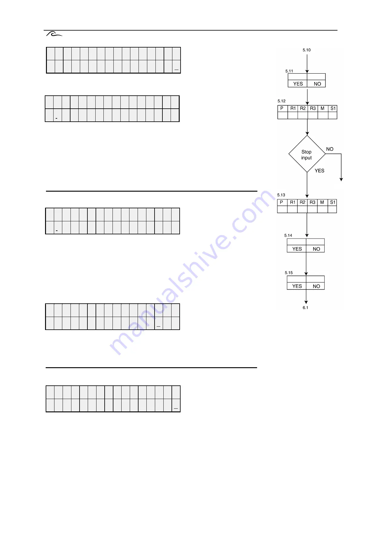
Stop
Define the phases in which
the "stop" input should be
active (see programming
step 10.1).
"|" Input is active
"
-
" Input is inactive
Press INFO to see the meaning of the abbreviation in plain text.
P
= Production phase
R3 = Rinse during production phase
R1 = Rinse after production phase
M
= Maintenance phase
R2 = Rinse during standby phase
S1 = Standby phase 1
Stop manual start
If the stop manual start
option is set to "Y" (yes),
the "stop manual start" LCD
comes on when the stop
input is activated. The system must be restarted again by pressing "ON".
If the stop manual start option is set to "N" (no), the "Signal stop " LCD comes
on when the stop input is activated. The system continues its normal
functions as soon as the stop signal at the input is cleared.
Power failure
You can program whether the system should remain
in the "standby stop" phase if a power failure occurs
or commence its normal cycle immediately, com-
mencing in general with a rinse phase.
All inputs are deactivated and no outputs are acti-
vated during the "standby stop" phase. The system must be started manually.
WARNING! If a power failure occurs during the "maintenance" phase, the controller returns to the
"stop maintenance" phase. If a code number has been defined for the maintenance phase, this must
be re-entered before the maintenance phase can be restarted.
Í ¬
» °
² ± ò
æ
ë ò
ï ï
ß « ¬
ò
- © ·
¬
½ ¸
± ² Ç ñ
Ò
Í ¬
» °
² ± ò
æ
ë ò
ï î
Ð ¤
Î ï ¤
Î î ¤
Î í ¤
Ó ¤
Í ï ¤
Í ¬
» °
² ± ò
æ
ë ò
ï í
Ð ¤
Î ï ¤
Î î ¤
Î í ¤
Ó ¤
Í ï ¤
Í ¬
» °
² ± ò
æ
ë ò
ï ì
Í ¬
± ° Ø ¿ ² ¼ - ¬
¿ ® ¬
Ç ñ
Ò
Í ¬
» °
² ± ò
æ
ë ò
ï ë
Í ¬
± °
- « ° ò
º
¿ ·
´
Ç ñ
Ò


