Design and function
Interfaces
46
099-005214-EW501
19.05.2011
5.10.1
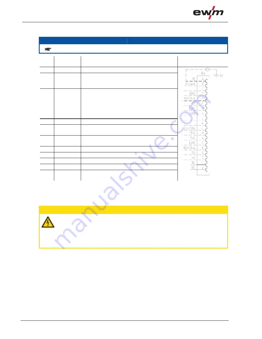
Automation interface
NOTE
These accessory components can be retrofitted as an option, see Accessories chapter.
Pin Input
/
output
Description Diagram
A
Output
PE
Connection for cable shielding
D
Output
(open
collector)
IGRO
Current flows signal I>0 (maximum load 20
mA / 15 V)
0 V = welding current flows
E
+
R
Input
Not/Aus Emergency stop for higher level shut-down
of the power source.
To use this function, jumper 1 must be
unplugged on PCB M320/1 in the welding
machine. Contact open
=
welding current
off
F
Output 0
V
Reference
potential
G/P
Output I>0
Power
relay
contact, galvanically isolated
(max. +/-15 V / 100 mA)
H
Output
Uist
Welding voltage, measured against pin F,
0-10 V (0 V = 0 V; 10 V = 100 V)
L
Input
Str/Stp Start = 15 V / Stop = 0 V
1)
M
Output
+15 V
Voltage supply (max. 75 mA)
N
Output
-15 V
Voltage supply (max. 25 mA)
S
Output 0
V
Reference
potential
T
Output
Iist
Welding current, measured on pin F;
0-10 V (0 V = 0 A, 10 V = 1000 A)
1
) The operating mode is given by the wire feed unit (the start / stop function equates to pressing
the torch trigger and is used in mechanised applications, for example).
5.10.2
PC Interfaces
CAUTION
Equipment damage or faults may occur if the PC is connected incorrectly!
Not using the SECINT X10USB interface results in equipment damage or faults in signal
transmission. The PC may be destroyed due to high frequency ignition pulses.
• Interface SECINT X10USB must be connected between the PC and the welding machine!
• The connection must only be made using the cables supplied (do not use any additional
extension cables)!
PC 300 welding parameter software
Create all welding parameters quickly on the PC and easily transfer them to one or more welding
machines (accessories: set consisting of software, interface, connection leads).


