5
Commissioning
5/2
5.3
Welding machine cooling system
Observe the following to attain the optimum duty cycle of the power components:
•
Ensure that the working area is adequately ventilated,
•
Do not obstruct the machine’s air inlets and outlets,
•
Metal parts, dust or other foreign bodies must not get into the machine.
5.4
Workpiece lead
Remove paint, rust and dirt from clamping and welding areas with a wire brush! Attach the
workpiece clamp in the immediate vicinity of the welding position! Structural parts, pipes,
rails etc. may not be used as return leads for the welding current if they are not the
workpiece themselves!
A perfect current connection must be ensured where welding benches and appliances are
concerned.
•
Insert cable plug of the workpiece lead into the welding current socket (Chap.2, B
)
and lock by
turning to the right.
MMA welding:
The polarity depends on the instructions of the electrode manufacturer on the electrode
packaging.
5.5
Electrode holder connection (MMA welding)
•
Insert cable plug of the stick electrode holder into the welding current socket "+" (Chap. 2, B
)
or
"-" (Chap. 2, C"
)
and lock by turning to the right.
The polarity depends on the instructions of the electrode manufacturer on the packaging.
5.6
General information on connection of the welding torch
We can only guarantee the perfect functioning of our machines when they are used with
our range of welding torches.
TIG welding torches with a shielded torch trigger control line should not be connected!
1.
The welding machines are supplied as standard with torch trigger pin assignment B1 and gas
connection G1/4" (only decentralised).
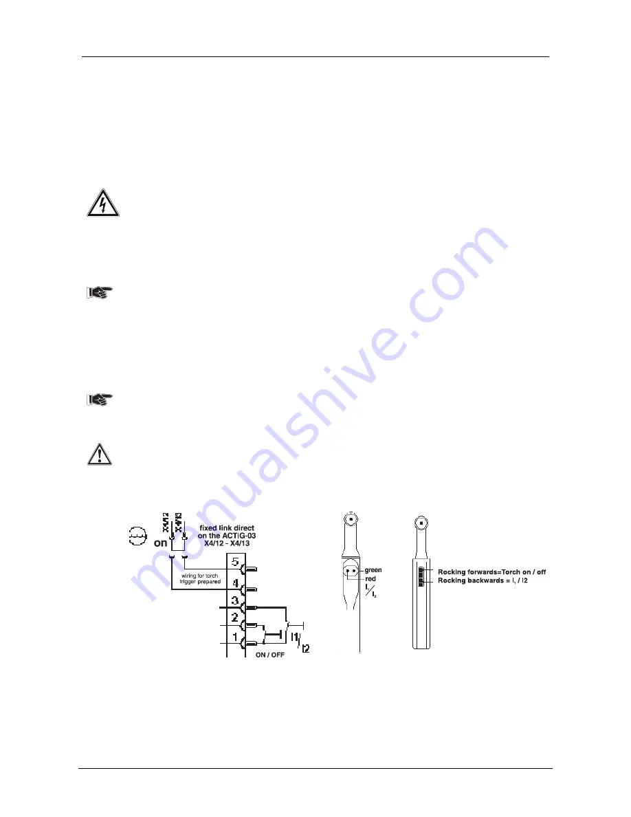
Fig. 2:
Connection socket connection B1
Fig. 3
Torch trigger variations
Torch trigger "BT" on PIN 1 / 2
Secondary current "I1 / I2" on PIN 1 / 3


