CONV Bosch To Pelco - firmware 0.01.xx
Ewimar Sp. z o.o.
www.ewimar.pl
Made in Poland
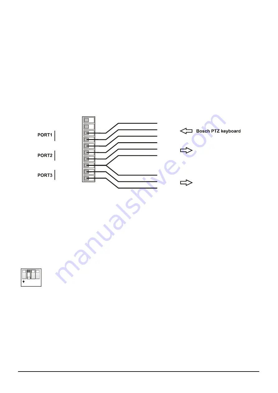
POWER / COMMUNICATION PORTS
– Removable terminal containing converter power terminals and
RS-485 / BIPHASE communication ports. The purpose of each port is described below.
LED DIODES
.
Red
– depending on the settings, informs about translation and sending data to the camera
or
informs about corrupted data packets / collisions, coming from the control device.
Green
– depending on the settings informs about any data coming from the control device
or
about the correct packets only (correct protocol and transmission parameters). Signaling that
the correct packets have been received does not mean that they will be translated, because it
also depends on settings the supported addresses by the converter.
DIP SWITCHES
– Designed to switch on termination resistors for ports 1 ~ 3 and to run the converter
firmware update mode.
USB
– It is designed to configure settings using the Firmware Upgrader / Configurator and to perform
software updates / changes
Power AC/DC
Power AC/DC
485 - A(+)
1
10
485 - B(-)
GND
485 - A(+)
485 - B(-)
GND
485 - A(+)
485 - B(-)
}
}
}
Pelco Speed Dome
Pelco Speed Dome
C+
C-
GND
A
B
GND
A
B
GND
POWER
- Connect a power source in the range
9 ~ 24V AC / DC
- any polarity.
GND
– Power Ground communication ports. It is recommended to connect with cameras and keyboards
to avoid damage due to the ground loop effect.
PORT1
– Configurable input port for connecting a PTZ keyboard with Bosch OSRD (RS-485) or Bosch
Biphase. When OSRD is chosen also baudrate adjust is avaiable by Configuration software (by
default: Pelco-D, 9600baud).
PORT2
– Output port do Speed Dome cameras with Pelco protocols.
PORT3
– Output port do Speed Dome cameras with Pelco protocols.
DIP-SW
1 2
4
3
ON
Dip switches No
1~3
are designed to turn on termination resistors accordingly for ports
1~3
. After set to ON, internal 120
Ω
resistor is connected between A and B of according
port.
Dip switch No 4 is used to emergency firmware update if during normal update
communication has been lost. This way to repair broken firmware. To activate emergency
update mode set DIP No 4 to
ON
and restart power supply (reconnect the USB). For
normal operation DIP No 4 must be in
OFF
position. Emergency update method has been
decribed in manual of the Firmware Upgrader / Configurator.


