background image

9

2551 Blind Magmeter

Sensitivity

•  The SENSITIVITY setting determines how the 2551 

responds to sudden surges in the fl ow rate. It "overrides" 
the Averaging function just long enough to allow an actual 
change in fl ow rate to be displayed, then resumes the 
averaging. The result is a smooth fl ow display and a quick 
response to large shifts in the fl ow rate.

•  The settings for Sensitivity represent a percentage of the 

magmeter's maximum range, or 10 meters per second (m/s).

•  Example: A sensitivity setting of 25% means that the fl ow 

rate must change instantly and by more than 2.5 ms before 
the function is enabled.

NOTE:

 The SENSITIVITY function is ineff ective if the 

AVERAGING function is set to zero.

Averaging

•  The AVERAGING setting dictates the time over which the 

magmeter will average the fl ow signal.

•  The LCD display is updated every second. With averaging 

at 14 seconds, the fl ow rate on the display is an average of 
the previous 14 seconds input.

•  Short averaging times provide the fastest display and output 

response to changes in the fl ow rate.

•  Higher averaging times help to smooth the display and 

current output where the fl ow in the pipe is erratic or 
unstable due to installation limitations.

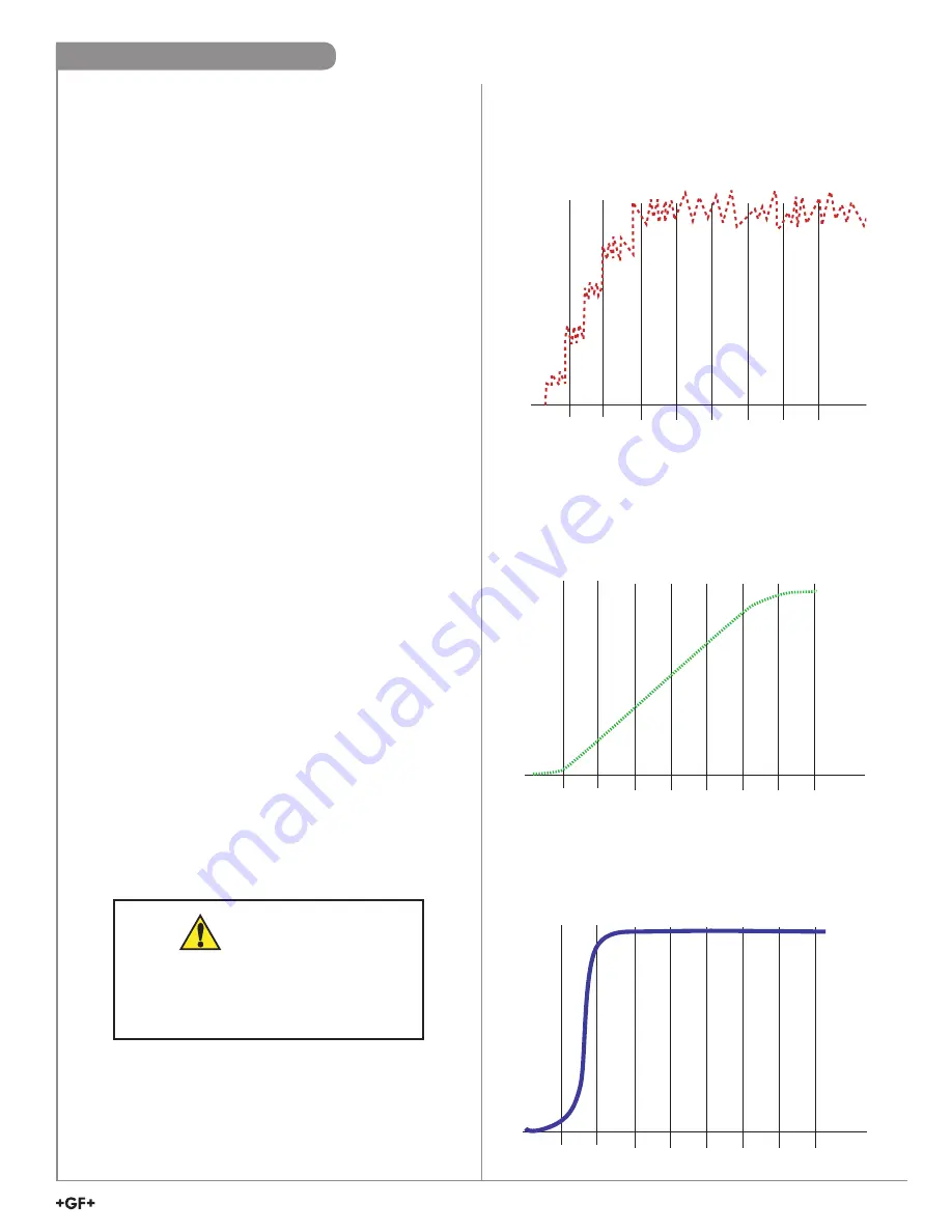
No Averaging

With AVERAGING set to zero, the fl ow rate will be displayed 
immediately and with no fi ltering. This line represents the 
actual output of the fl ow sensor as it responds to unstable fl ow 
conditions in the pipe.

10 s

20 s

30 s

40 s

50 s

60 s

70 s

Time

Ve

locity

Averaging Only

With AVERAGING set to 50 seconds and SENSITIVITY still 
set to zero the fl ow rate is stabilized, but a sharp change in 
fl ow rate is not represented on the display or at the output for 
50 seconds or longer.

10 s

20 s

30 s

40 s

50 s

60 s

70 s

Time

Ve

locity

Averaging and Sensitivity

With AVERAGING at 50 seconds and SENSITIVITY set to 
25%, the fl ow rate is stabilized, while the sudden shift in fl ow 
is refl ected very quickly.

10 s

20 s

30 s

40 s

50 s

60 s

70 s

Time

Ve

locity

Even the most carefully engineered fl ow systems may 
experience  erratic and unstable conditions. If the instability is 
communicated to the output functions, the results may create 
problems for control devices.

To alleviate these issues, the 2551 provides two adjustments 
that operate in tandem. The information here will help 
in determining the appropriate settings for any specifi c 
application.

Averaging and Sensitivity

The SENSITIVITY function changes the 
response characteristics of the magmeter. 
If used as part of a tuned closed loop control 
system, such a change may be undesirable.

CAUTION

Summary of Contents for Neptune Benson Defender FP Series

Page 1: ...INSTALLATION FOSS SWIM SCHOOL AND ACCESSORIES ELMWOOD PARK FILTER SYSTEM an QUA brand evo 334 Knight St Suite 3100 West Warwick RI 02886 800 832 8002 401 821 2200 Fax 401 821 7129 E mail infowebsite...

Page 2: ...M LYNCH 14DEC21 INIT DYMNYR FOSS SWIM SCHOOL ELMWOOD PARK SWIMMING POOL FOSS SWIM SCHOOL LLC 35452 1 1 1 18 GPM SQ FT 252 GPM NTS...

Page 3: ...Defender FP Series Featuring PowerBump System Installation and Operation Manual Phone 800 832 8002 Web www neptunebenson com www defenderfilter com...

Page 4: ...tallation 16 Operation 17 System Requirements 17 Pre Startup Check 17 Performing a Dry Test 17 Performing a Quick Start 18 Loading Media into the System Precoat Process Vacuum Transfer 18 Entering Fil...

Page 5: ...wer bump valve V3 Power bump valve V4 Power bump valve V5 Precoat valve V6 Vacuum transfer valve V7 Vacuum vent valve V8 Vacuum hose valve V9 Tank drain valve V10 Check Valve 4 or 6 V11 In line sight...

Page 6: ...tial of skin burn injury exists when handling or servicing the pnuematic actuators and pump when on or shortly after stopping the system Use caution around the system and avoid the heated areas during...

Page 7: ...to the floor Anchors must be installed per the manufacturer s instructions before attempting to lift the filter head top plate Failure to properly bolt the filter to the floor can result in bodily inj...

Page 8: ...nting bracket by inserting the longer flange bolts through the channel in the bracket and secure with 0 75 inch nuts included 4 Bolt the gauge panel to the mounting bracket using four 0 25 x 1 inch sc...

Page 9: ...4 Control Enclosure and Filter Regulator 0 5 inch hard pipe from compressor Do not use PVC not included 0 5 inch shut off valve not included 0 5 inch instant fitting 0 5 inch hose to solenoid Manifol...

Page 10: ...t protection supplied by others Recommended protection is 120 230 VAC 15 10 A Line Power Connect to TERMINAL 100 Neutral Connect to TERMINAL 100A Ground Connect to GROUND LUG located at the upper righ...

Page 11: ...fected parts 1 Attach the filter regulator to a wall using anchors compatible with the type of wall construction Block plaster wood etc The anchors are not included 2 Add an isolation valve before the...

Page 12: ...Page 10 26 Rev 01 18 2021 Installing the Butterfly Valves...

Page 13: ...Page 11 26 Rev 01 18 2021 Making the Pneumatic Actuator Tubing Connections Figure 7 Pneumatic Tubing Diagram...

Page 14: ...pneumatic actuators as included in valve kit 1002 1214 1002 1543 If using any other actuator consult your system designer on proper actuator installation Air to OPEN valve Valve disc position indicat...

Page 15: ...trix NOTE After making pneumatic actuator connections raise the air pressure to 90 psi and confirm the valve positions match the Idle state presented in the valve matrix table above If a valve state i...

Page 16: ...Control Valves Adjustment Figure 11 Flow Control Valves Pneumatic actuators are provided with the flow control valves The flow control valves connected to the pneumatic actuators are used to regulate...

Page 17: ...s for smooth operation To make this adjustment 1 The control valve on the closed port regulates the butterfly valve s opening speed 2 The control valve on the open port regulates the butterfly valve s...

Page 18: ...Rev 01 18 2021 Vacuum Transfer Unit Installation Figure 12 Vacuum transfer setup NOTE Most standard shop style vacuums will be appropriate for loading media A vacuum can be provided by Neptune Benson...

Page 19: ...ed Refer to Installing the Control Panel and Filter Regulator Set the filter regulator to 90 PSI 6 2 Bar Pump rotates in the proper direction and is ready to run Performing a Dry Test 2 With the pump...

Page 20: ...lve V6 10 Open the 0 75 inch precoat vent line valve F6 and 1 5 inch vacuum drain line valve V7 11 Open pump discharge throttling valve F7 and purge the air from the system NOTE If the filter is below...

Page 21: ...load and other factors the media might require recharging anywhere between 2 weeks and 3 months The exact frequency will become apparent as operating experience with the system increases The following...

Page 22: ...Every 3 months Refer to the manufacturer s owner s manual for details When replacing the airline filter element use SMC Corporation Part AF40P 060S Flexible tube cleaning Varies depending on bather l...

Page 23: ...y turning the switch on the PowerBump Control Panel to the left OFF 2 Loading Media into the System Precoat Process Vacuum Transfer 3 Purge the air from the system 4 Switch to Filter Mode 5 Precoat fo...

Page 24: ...nother gasket on top of the tube sheet assembly 12 Place the filter head onto the gasket 13 Connect the filter head to the tank using the fasteners with 1 1 8 wrench Tighten the fasteners to 20 ft lb...

Page 25: ...Page 23 26 Rev 01 18 2021 Parts List Assembly Exploded View Figure 15 Exploded View 8 3 6 7 5 4 2 17 16 15 13 14 11 12 10 4 9 1 20 22 21 18 19 22 23 24...

Page 26: ...ENDER TUBE ELEMENT 36 T316 366 1000 7552 10 TUBESHEET PLATE PVC BOTTOM FP SERIES 1 1002 1160 11 HOLD DOWN PLATE PVC TUBESHEET FP SERIES 1 1002 1161 12 GASKET FELT F TUBESHEET COMPACT DEFENDER 1 1002 1...

Page 27: ...assembly into the flange pipe so that the flow openings are facing downward inside the filter 3 Install a second gasket between the diffuser and flange connected to the installation piping 4 Tighten...

Page 28: ...n presented herein is believed reliable and in accordance with accepted engineering practices Evoqua makes no warranties as to the completeness of this information Users are responsible for evaluating...

Page 29: ...magnetic ow sensor The patented sensor design is available in a variety of corrosion resistant materials to provide long term reliability and minimal maintenance costs Wetted material combinations inc...

Page 30: ...20 F C 4 32 68 104 140 176 212 248 Operating Temperature Pressure Dimensions Refer to your local Georg Fischer Sales o ce for the most current warranty statement All warranty and non warranty repairs...

Page 31: ...nd 316L SS T0 T1 T2 PVDF and Titanium V0 V1 V2 PVDF and Hastelloy C O rings FKM standard EPDM FFKM optional The user is responsible for determining the chemical suitability of these materials for a sp...

Page 32: ...GF OK OK OK Vertical flow is OK if the pipe remains full at all times Type Description Plastic tees 0 5 in to 2 in versions MPVC or CPVC PVC Glue on Saddles 10 in and 12 in only Cut 2 in hole in pipe...

Page 33: ...Earth Ground Terminal Flow Important The directional arrow on the sensor body MUST be pointed DOWNSTREAM for correct operation Digital S3 L and 4 to 20 mA will not work if ow is against direction of...

Page 34: ...metal clamps on metal pipes Fluid grounds must be in direct contact with the uid and as near to the Magmeter as possible 3 The shield from the output cable must be terminated at the remote instrument...

Page 35: ...to indicate reverse ow The maximum cable length from the 2551 to the 8900 or 9900 depends on the 8900 or 9900 con guration Refer to the 8900 9900 or 9950 manual for complete information Blue Jumper O...

Page 36: ...d performance settings are pre set to meet the requirements of most applications The 2551 application and performance settings can be customized using the Signet 3 0252 Con guration Tool and software...

Page 37: ...stallation limitations No Averaging With AVERAGING set to zero the ow rate will be displayed immediately and with no ltering This line represents the actual output of the ow sensor as it responds to u...

Page 38: ...VC TEES FOR SCH 80 CPVC PIPE 1 2 MCPV8T005 2496 03 659 45 12 45 3 4 MCPV8T007 1381 48 364 99 22 84 1 MCPV8T010 857 98 226 68 37 139 1 1 4 MCPV8T012 445 17 117 61 66 248 1 1 2 MCPV8T015 325 56 86 01 90...

Page 39: ...DN15 PVMT005 2067 76 546 30 18 68 DN20 PVMT007 1136 61 300 29 28 106 DN25 PVMT010 716 52 189 31 46 174 DN32 PVMT012 446 07 117 85 72 272 DN40 PVMT015 278 83 73 67 113 428 DN50 PVMT020 159 36 42 10 17...

Page 40: ...67 378 1433 4 CS4W040 36 38 9 61 652 2469 5 CS4W050 29 28 7 73 1024 3877 6 CS4W060 20 29 5 36 1480 5601 8 CS4W080 11 73 3 10 2557 9680 10 CS4W100 7 45 1 97 4032 15262 12 CS4W120 5 24 1 39 5725 21671 G...

Page 41: ...agmeter Use 3 0252 Setup tool to re span the Magmeter to match Loop device Re span Loop device to match Magmeter Range Jumper not placed correctly Set Range Jumper correctly Defective Magmeter Return...

Page 42: ...empty pipe Frequency output will be locked to 0 Hz if electrodes are not wet Digital S3 L output will be locked to 0 if electrodes are not wet 4 to 20 mA will be locked to 4 mA if electrodes are not...

Page 43: ...placement Electronics Module 3 2551 11 159 001 215 Magmeter electronics frequency or digital S3 L output 3 2551 12 159 001 216 Magmeter electronics 4 to 20 mA output 3 2551 21 159 001 372 Magmeter dis...

Page 44: ...8 in PVDF and Hastelloy C 3 2551 P2 12 159 001 112 DN250 to DN900 10 to 36 in Polypropylene and 316L SS 3 2551 T2 12 159 001 449 DN250 to DN900 10 to 36 in PVDF and Titanium 3 2551 V2 12 159 001 451...

Page 45: ...lve V6 3 Open Precoat Line Vent Valve F6 50 4 Open Vacuum Vent Valve V7 50 5 Open Pump Discharge Throttling Valve F7 6 Turn Filter Switch ON on Control Panel 7 Close Vacuum Vent Valve V7 when water ex...

Reviews: