31
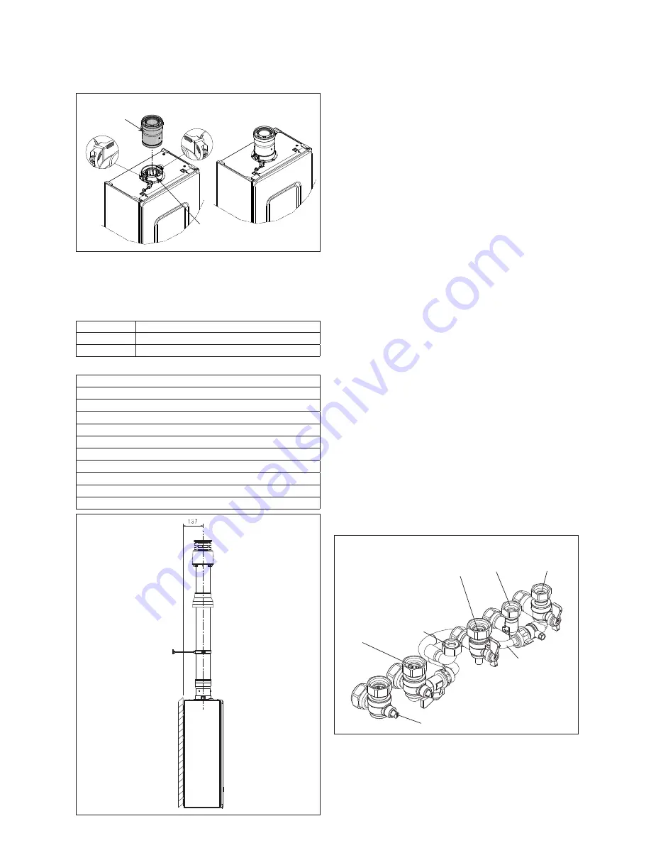
clicks into position (this is when the tabs at points ‘
A
’ are located
in the groove of the vertical flue connector - see fig. 18). Both
screws (
C
) should now be tightened.
NOTE:
If more convenient, the vertical flue connector can be
attached to the vertical flue terminal/extension before connecting
it to the appliance.
vertical
connection
A
A
C
C
B
flange installed
as standard
Fig.18
NOTE
Additional bends and/or extensions can be connected to the
terminal connector if desired, however if additional bends are
fitted, a reduction must be made to the maximum flue length
(see table below).
Reduction for bends
Bend
Reduction in maximum flue length for each bend
45º bend
1.0 metre
90º bend
1.0 metre
Vertical flue terminal and accessories
Code
Description
Length
20122763 Vokera XV Vertical Flue kit
1000mm
29450123 90-degree bend
N/A
29450124 45-degree bends (2)
N/A
29450125 500mm extension
500mm
29450126 1000mm extension
1000mm
29450127 2000mm extension
2000mm
29450128 Telescopic extension
372/519mm
529
100mm flue brackets (5)
N/A
531
Pitched roof flashing
N/A
532
Flat roof flashing
N/A
Fig. 19
IMPORTANT
The vertical flue terminal is 1.0 metre in length and cannot be
cut; therefore it may be necessary to adjust the height of the
appliance to suit or use a suitable extension.
5.6 CONNECTING THE GAS AND WATER
The appliance is supplied with an accessory pack that includes
service valves. The service valves are of the compression type.
The accessory pack contains sealing washers’ etc, for use with
the service valves. When connecting pipe work to the valves,
tighten the compression end first then insert the sealing washers
before tightening the valve to the appliance.
NOTE
It will be necessary to hold the valve with one spanner whilst
tightening with another.
5.6.1 GAS (fig. 20)
The appliance is supplied with a 15mm service valve, connect
a 15mm pipe to the inlet of the valve and tighten both nuts.
NOTE
It will be necessary to calculate the diameter of the gas supply
pipe to ensure the appliance has an adequate supply of gas.
5.6.2 FLOW & RETURN (fig. 20)
The appliance is supplied with 22mm service valves for the
flow and return connections, connect a 22mm pipe to the inlet
of each valve and tighten both nuts.
NOTE
Depending on system requirements, it may necessary to increase
the size of the flow & return pipe work after the service valve
connections.
5.6.3 COLD WATER INLET (fig. 20)
The appliance is supplied with a 15mm combined stopcock and
filling valve, connect a 15mm pipe to the inlet of the stopcock
and tighten both nuts.
5.6.4 HOT WATER OUTLET (fig. 20)
The appliance is supplied with a 15mm outlet connection, connect
a 15mm pipe to the outlet connection and tighten both nuts.
5.6.5 SAFETY VALVE (fig. 20)
Connect the safety valve connection pipe to the safety valve
outlet and tighten. The discharge pipe must have a continuous fall
away from the appliance to outside and allow any water to drain
away thereby eliminating the possibility of freezing.
The discharge pipe must terminate in a position where any water
- possibly boiling - discharges safely without causing damage or
injury, but is still visible.
Fig. 20
Hot water
outlet
Cold water
inlet
stopcock
C/H return valve
C/H flow
valve
Safety valve
outlet
Gas
cock
Filling loop
5.6.6 CONDENSATE DISPOSAL
This appliance will - under normal operating conditions - produce
condensate fluid that will require to be disposed of via the
dwelling’s waste water drainage system.
Vokera strongly recommends that the condensate pipe is
connected to the internal waste water pipework in accordance
with BS6798.


