24
www.evolutionpowertools.com
Turn the vertical handle counter-clockwise to unlock the mitre
gauge, and adjust to the required angle. Turn the handle clockwise
to lock the mitre gauge at the chosen angle.
Note:
The extruded aluminium faceplate of the mitre gauge
should be adjusted so that it passes close to, but does not touch
the blade or blade guard. Adjust the faceplate by loosening the
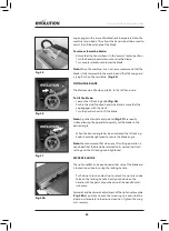
two wing nuts
(Fig. 32)
and slide the faceplate to the required
position. Securely tighten the wing nuts.
WARNING:
Conduct a ‘dry run’ with the machine disconnected
from the mains supply to ensure that the mitre gauge does indeed
slide passed the blade and blade guard without any interference.
ANTI-BOUNCE DEVICE
Note:
When cutting thin sheet or similar material the
anti-bounce device can be usefully employed.
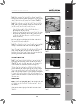
(Fig 33)
Insert the anti-bounce device into the socket provided in the mitre
gauge. Position the anti-bounce device for optimum efficiency
and secure in place using the thumb screws.
Adjust the anti-bounce device so that the head does not quite
touch the material to be cut. You can achieve this by gently
clamping the material to be cut with the anti-bounce device, and
then backing off the head by 1/2 to 1 turn.
Note:
When the machine is not in use, the mitre gauge & anti-
bounce device has dedicated storage on the right hand side of the
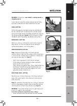
machine body (Fig 34).
Raise the anti-bounce device and rotate it anti-clockwise until it is
next to the mitre locking knob, then lower until it makes contact
with the mitre gauge. Position the mitre gauge to the far left hand
side of the aluminium face plate and secure. Push the extruding
face plate into the slot provided on the right hand side
machine body.
BASIC TABLE SAW OPERATIONS
WARNING:
Never attempt freehand cuts on this machine. Always
use the appropriate guide or fence to minimise the possibility of
the blade binding and/or kickback occurring.
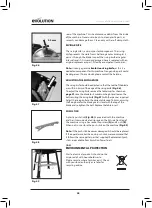
We recommend that the saw blade protrudes through the
material to be cut by approximately 3mm.
(Fig. 35)
Adjust the
height of the blade accordingly.
Fig. 33
Fig. 34
Fig. 35
Fig. 32


