27
www.evolutionpowertools.com
EN
ES
DE
FR
IT
NL
BEVEL RIPPING
Bevel ripping is cutting along the length of a work-piece with
the saw blade tilted at an angle.
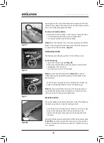
When bevel ripping material 150mm or narrower use the
rip fence on the RH side of the blade only.
(Fig 42)
MAINTENANCE
WARNING:
Ensure that the machine is disconnected from the
mains supply before any maintenance tasks or adjustments
are attempted.
CHANGING THE BLADE
Note:
We recommend that the operator considers wearing
protective gloves when handling or changing the machines blade.
• Disconnect the machine from the power supply
• Remove the top blade guard.
(refer to TOP BLADE GUARD
on page 20)
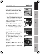
• Remove the table access plate by removing the countersunk
head screw from the front edge of the access plate.
(Fig. 43)
• Lift the plate away and carefully store it and its fixing screw
for future use.
• Raise the blade to its highest position.
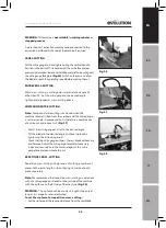
• Use the two blade changing spanners provided. One spanner
will fit the hexagonal nut machined onto the outer blade
flange, and thus prevent the arbor from rotating. The other
spanner will fit the arbor nut.
(Fig 44)
• Remove the arbor nut, the outer blade flange and the blade.
• Thoroughly clean any debris from these parts and also from
the exposed motor arbor and inner blade flange. The inner
blade flange can be left in situ.
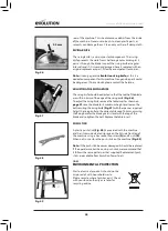
• Fit the new blade. Ensure that the teeth are facing to the
front of the saw
(Fig. 45),
and that the rotation arrow on
the blade is in conformism with the rotation arrow on the
motor housing.
• Replace the outer flange and nut and tighten securely with
the spanners provided. Check that both blade flanges are in
contact with the blade.
• Replace the table access plate and its fixing screw.
Ensure that the fixing screw is correctly seated.
• Replace the top blade guard.
CLEANING
After each use the machine should be cleaned. Remove all
sawdust, etc from the visible parts of the machine with a
workshop vacuum cleaner. A workshop dust extraction can
also be connected to the machine dust extraction port at the
Fig. 42
Fig. 43
Fig. 44
Fig. 45


