19
EvoHeat Fusion-i Series Manual
8. Appendix
8.1 Interface Drawings
(1) Main Board – Fusion i7/ Fusion i9/ Fusion i12
Page 1: ......
Page 2: ..._________________ 12 6 2 Functions of the Controller _____________________________________________________________________ 13 6 2 1 Start up Shutdown __________________________________________________...
Page 3: ...h minimal running costs Designed with the latest technology including stepless full DC inverter compressors fans and control systems the Evo Fusion i is the energy efficient and environmentally friend...
Page 4: ...3 EvoHeat Fusion i Series Manual 2 Unit Dimensions Unit mm Fusion i 7 9 12...
Page 5: ...4 EvoHeat Fusion i Series Manual Fusion i 16 Fusion i 19...
Page 6: ...rubber pads under the feet of the unit 3 Install the supplied condensation barb to the underside of the unit and direct the condensation to an appropriate drainage point PLUMBING INSTALLATION PLEASE...
Page 7: ...tart within 60 seconds 4 To select the operating mode press the M button to cycle to the sun icon heating 5 To set the temperature press in the main interface the current target temperature will flash...
Page 8: ...0mA residual current device RCD having a rated residual operating current not exceeding 30mA and disconnection must be incorporated in the fixed wiring in accordance with the wiring rules The unit sho...
Page 9: ...censed installer will void the warranty Correct installation is required to ensure safe and efficient operation of your pool heater Before installation it is very important to ensure 5 variables are c...
Page 10: ...of to be forced through the unit A water deflector may be needed to protect the heat pump If installing the heater on an existing pump filtration system the heater must be installed AFTER the filter a...
Page 11: ...flow than required to the heat pump 5 6 Rubber Feet All EvoHeat units are provided with rubber feet which EvoHeat highly recommend being installed The rubber feet help reduce vibration of the unit and...
Page 12: ...read the information before connecting Ensure the power cable and circuit breaker are of a suitable size for the heater being installed Also check that there is adequate voltage and current available...
Page 13: ...is locked HEATING Heating mode is active FAULT Displays when a fault occurs AUTO Auto mode is active WIRELESS Appears if the unit is connected to wifi and shows the strength of the signal accordingly...
Page 14: ...rding to what mode is active After 2 seconds without a change the setting will be saved If the unit is defrosting the defrosting symbol will display on the main interface After defrosting is complete...
Page 15: ...e is no operation for 20 seconds the system will automatically memorise the settings and return to the main menu Press the ON OFF button at any time during changes to exit without saving changes 6 2 5...
Page 16: ...n to activate the one click silent function If the one click silent and timing silent function are both started at the same time press MUTE to cancel the one click silent unction and quit the timing s...
Page 17: ...s from the main menu hold the ON OFF button for around 5 seconds The keyboard will be locked when the small lock symbol appears The screen can be locked while the controller is in the on or off interf...
Page 18: ...freezing Prot E29 The ambient temp Is low Inlet and outlet temp too big E06 Water flow is not enough and low differential pressure Check the pipe water flow and whether water system is jammed or not...
Page 19: ...e input voltage measurement Inv Sampling Volt F11 The input voltage sampling fault Check and adjust the current measurement Comm Err DSP PFC F12 DSP and PFC connect fault Check the communication conne...
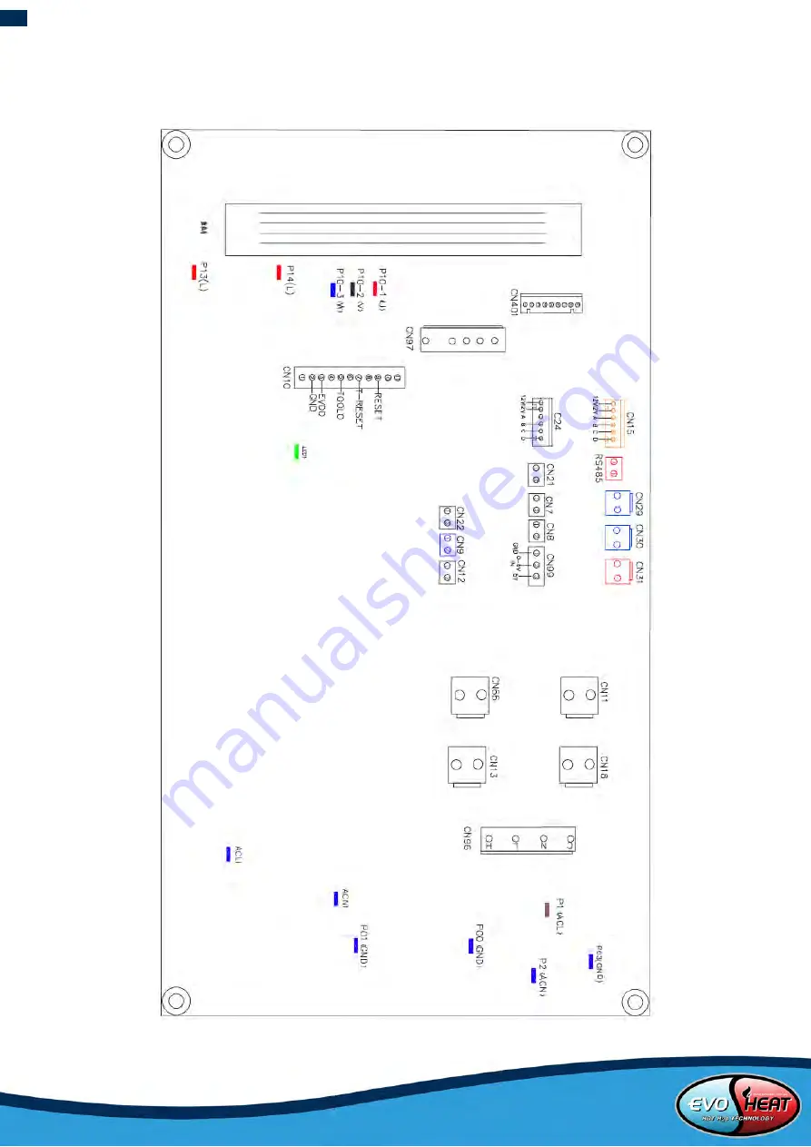
Page 20: ...19 EvoHeat Fusion i Series Manual 8 Appendix 8 1 Interface Drawings 1 Main Board Fusion i7 Fusion i9 Fusion i12...
Page 21: ...20 EvoHeat Fusion i Series Manual 2 Main board Fusion i16 Fusion i19...
Page 22: ...HT System exhaust temperature input 20 P00 GND Earth wire 21 P01 GND Earth wire 22 P13 L P14 L Electric reactor 23 R485 B R485 A Color line controller communication 24 CN15 Electronic Expansion valve...
Page 23: ...m2 25mm2 125A 101 123A 2 x 35mm2 35mm2 160A 123 148A 2 x 50mm2 50mm2 225A 148 186A 2 x 70mm2 70mm2 250A 186 224A 2 x 95mm2 95mm2 280A If the unit is to be installed outdoors ensure that a UV resistant...
Page 24: ...should I be checking regularly Check the water inlet outlets often for leaks You should avoid the condition of no water or air entering into the system as this will influence unit s performance and r...
Page 25: ...sible ignition sources including cigarette smoking should be kept sufficiently far away from the site of installation repairing removing and disposal during which flammable refrigerant can possibly be...
Page 26: ...most critical point to warn of a potentially hazardous situation 2 Particular attention shall be paid to the following to ensure that by working on electrical components the casing is not altered in...
Page 27: ...by cutting or brazing The refrigerant charge shall be recovered into the correct recovery cylinders The system shall be flushed with OFN to render the unit safe This process may need to be repeated se...
Page 28: ...late system electrically c Before attempting the procedure ensure that Mechanical handling equipment is available if required for handling refrigerant cylinders All personal protective equipment is av...
Page 29: ...g or damage to the product in transit 4 If warranty service is required you should a contact Evo Industries Australia on 1300 859 933 or via our Contact page on our web site b provide a copy of your r...