background image


b.


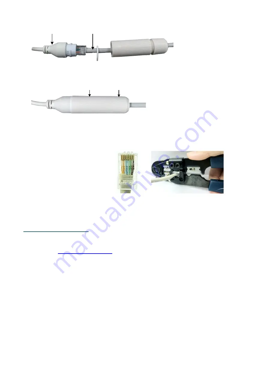
Connect the RJ-45 cable to the 

LAN/PoE Cable

 of the camera. 

RJ-45 Cable

LAN/PoE Cable


c.


Tightly screw the 

Cable Gland

 and 

Screw Cap

 to the Rugged RJ-45 

Connector Cable. 

Screw Cap

Cable Gland


d.


Crimp the RJ-45 connector onto the RJ-45 network cable. Note that the 

wires should be placed into the RJ-45 connector based on the following 

order (from left to right). 

Orange with white stripe

Orange

Green with white stripe

Blue

Blue with white stripe

Green

Brown with white stripe

Brown


7.


Now you can access the camera live view. See 

4. Accessing the Camera

.   


4.


Accessing the Camera 

You can look up the IP address of the IP camera using the 

IP Utility (IPU) 

program from 

EverFocus website

 (key word search: "IP Utility"). 

The default network is DHCP. However, if there is no dynamic IP address 

assigned to the device, its IP will switch to 192.168.0.10. By default, the ID is 

admin

 and there is no password. Please input a password for the first-time login.   

Summary of Contents for EHN2550-SG

Page 1: ...images including product pictures or screen shots in this document are for example only The images may vary depending on the product and software version Information contained in this document is subj...

Page 2: ...is currently reserved and Zoom In Out 2 Sunshield Protect the camera from the direct sun rays 3 Tilt Screw Use the supplied Hexagon Wrench to loosen the Tilt Screw 4 Pan Screw Use the supplied Hexagon...

Page 3: ...7 Installation Sticker x 1 1 Camera x 1 2 Cable Gland Kit x 1 3 Screw x 4 4 Screw Anchor x 4 5 Torx Wrench x 1 6 Quick Installation Guide x 1 7 Installation Sticker x 1 Note 1 Equipment configuration...

Page 4: ...ons for network power audio input output and alarm input output Alarm Input Output LAN PoE Cable 12VDC Power Input Audio Output Audio Input Alarm IO PIN Assignment 1 2 3 4 Alarm In GND COM Alarm Out R...

Page 5: ...ew Anchors 2 Adjust the pan tilt rotate angles of the camera by loosen the Pan Tilt screws using the supplied Hexagon Wrench Tilt Screw Pan Screw 3 Connect the camera to power You can either connect t...

Page 6: ...te stripe Orange Green with white stripe Blue Blue with white stripe Green Brown with white stripe Brown 5 Optionally insert a Micro SD card into the card slot please refer to No 1 in 1 Physical Descr...

Page 7: ...d into the card slot please refer to No 7 in 1 Physical Description 4 Adjust the pan tilt rotate angles of the camera 5 Connect the camera to power You can either connect the camera to a 12VDC power s...

Page 8: ...with white stripe Orange Green with white stripe Blue Blue with white stripe Green Brown with white stripe Brown 7 Now you can access the camera live view See 4 Accessing the Camera 4 Accessing the C...

Reviews: