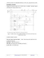
Installation guidelines for the POWERLINE GREEN 33 LITE UPS units in parallel/redundant operation
2016-10-27 11:56
Technical support
, tel.: +48 61 6500 400
www.ever.eu
10
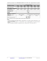
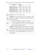
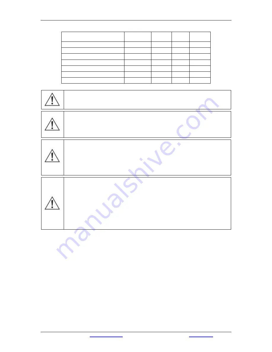
Table 3. Safeguards and wire sizes for single device
MODEL
Fm, Fb,
Fout
A
D
E
POWERLINE GREEN 33 LITE 10 kVA
20 A gG
2.5 mm
2
6 mm
2
6 mm
2
POWERLINE GREEN 33 LITE 15 kVA
25 A gG
4 mm
2
6 mm
2
6 mm
2
POWERLINE GREEN 33 LITE 20 kVA
32 A gG
6 mm
2
6 mm
2
6 mm
2
POWERLINE GREEN 33 LITE 30 kVA
50 A gG
16 mm
2
16 mm
2
16 mm
2
POWERLINE GREEN 33 LITE 40 kVA
63 A gG
16 mm
2
16 mm
2
16 mm
2
POWERLINE GREEN 33 LITE 50 kVA
80 A gG
25 mm
2
25 mm
2
16 mm
2
POWERLINE GREEN 33 LITE 60 kVA
100 A gG
35 mm
2
25 mm
2
16 mm
2
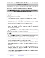
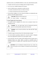
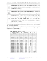
CAUTION!
Use LgY wires for the UPS cables
CAUTION!
Follow the phase rotation order when collecting the power
supply line. This applies to all components of the BYPASS switchboard
and the UPS connection.
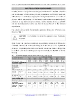
This UPS has been designed for operation in TN systems
The exact requirements are specified for a local UPS switching
room located directly at the device. Follow the applicable local
requirements when selecting the wire sizes.
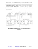
CAUTION!
Only trained personnel may switch power to the external
bypass system. Switching operations carried out against this procedure
may result in damage to the UPS. The external bypass system operation
is described in a separate documentation, "Instruction manual for the
bypass system of the POWERLINE GREEN 33 LITE UPS units in
parallel operation".
Summary of Contents for POWERLINE GREEN 33 LITE
Page 1: ......


