Issue 2, Nov-98. Applies to software versions 1.3 & 1.4 -10- HA026270
A
UTOMATIC
T
UNING
In PID control, the output from the controller is the sum of three
terms: Proportional, Integral and Derivative. These three terms
deliver just the right amount of power to hold the temperature at
setpoint without oscillation. For stable control, the PID values
must be ‘tuned’ to the characteristics of the process being
controlled. In the 2132 and 2116 this is done automatically using
advanced tuning techniques.
Automatic tuning is performed by switching the output of the
controller On and Off to induce an oscillation in the measured
temperature. From the amplitude and period of the oscillation, the
PID values, shown in the table below, are calculated.
Parameter
Display
Meaning or Function
Proportional
band
The bandwidth in
°
or
°
over which the output
power is proportioned between minimum and
maximum.
Integral time
Determines the time taken by the controller to
remove steady-state error signals.
Derivative
time
Determines how strongly the controller will react
to the rate-of-change of temperature.
Low cutback
The number of
°
or
°
below setpoint at which
the controller will cutback the output power to
prevent overshoot on heat up.
High
Cutback
The number of
°
or
°
above setpoint at which
the controller will increase the output power to
prevent undershoot on cool down.
Relative
cool gain
Only present if cooling has been configured.
Sets the cooling proportional band by dividing the
Pb value by the
value.
If the process cannot tolerate 100% heating or cooling during
tuning, the power can be restricted by the heating and cooling
limits in the Output list. However, the measured value must
oscillate to some degree for the tuner to determine values.
Tuning is normally performed only once during the initial
commissioning of the process. However, if the process under
control subsequently becomes unstable (because its characteristics
have changed), you can re-tune again at any time.
It is best to tune starting with the process at ambient temperature.
This allows the tuner to calculate more accurately.
Heating and Cooling Output Cycle Times
Before commencing a tuning cycle, set the values of
!$!%
(heating output cycle time) and
!$!! (cooling output cycle time)
in the
(output) list.
For a logic heating output (switching a SSR), set
!$!% to & sec.
For a relay output, set
!$!% to && sec.
For a logic cooling output used to control a solenoid valve, set
!$!! to & sec.
Tuning procedure
1. Set the setpoint to the value at which you will normally operate
the process.
2. In the ‘
’ list, select ‘'
’
and set it to
‘
’
3. Press the Page and Scroll buttons together to return to the
HOME display. The display will flash ‘
'’ to indicate that
tuning is in progress.
4. The controller will induce an oscillation in the temperature by
turning the heating on and then off.
5. After two cycles of oscillation the tuning will be completed
and the tuner will switch itself off.
6. The controller will then calculate the tuning parameters and
resume normal control action.
If you want ‘Proportional only’ or ‘P+D’ or ‘P+I’ control, you
should set the ‘
’ or ‘’ parameters to before
commencing the tuning cycle. The tuner will leave them off and
will not calculate a value for them.
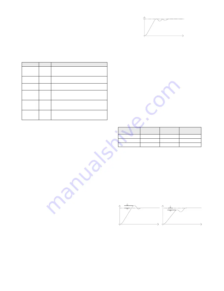
Typical automatic tuning cycle
Calculation of the cutback values
When low cutback or high cutback is set to ‘
(’ their values
will be fixed at three times the proportional band, and will not be
altered during automatic tuning. If set to any other value, they will
be calculated as part of the tuning process.
MANUAL TUNING
If for any reason automatic tuning gives unsatisfactory results, you
can manually tune the controller.
Proceed as follows:
With the process at its normal running temperature:
1. Set the Integral Time ‘
’and
Derivative Time ‘
’ to .
2. Set
High Cutback ‘
%)’ and Low Cutback ‘)’, to ‘’
3. Ignore the fact that the temperature may not settle precisely at
the setpoint
4. Reduce
the
proportional band ‘
)’ until the temperature just
starts to oscillate. If the temperature is already oscillating,
increase the proportional band until it just stops oscillating.
Allow enough time between each adjustment for the
temperature to stabilise. Make a note of the proportional band
value ‘B’ and the period of oscillation ‘T’.
5. Set the PID parameter values according to the formula below:
Type of control
Proportional
band ‘
’
Integral time
‘
’
Derivative time
‘
’
Proportional only
2xB
OFF
OFF
P + I
2.2xB
0.8xT
OFF
P + I + D
1.7xB
0.5xT
0.12xT
Setting the cutback values
The above procedure sets up the parameters for optimum steady
state control. If unacceptable levels of overshoot or undershoot
occur during start-up or for large step changes in temperature, then
manually set the cutback parameters
) and %).
Proceed as follows:
1. Set the low and high cutback settings to 3 x the proportional
band (that is to say,
) = %) = 3 x *).
2. Note the level of overshoot or undershoot that occurs for large
temperature changes (see the diagrams below).
In example (a) increase
) by the overshoot value. In example
(b) reduce
) by the undershoot value.
Example (a)
Example (b)
When the temperature approaches the setpoint from above, you can
set
%) in a similar manner.
Manual reset
When
= manual reset (' ) appears in the +
This parameter sets the output power when the error signal is zero.
It can be manually adjusted to remove steady state error - the
function normally performed by the Integral term.
Time
Temperature
Temperature
Time
Undershoot
Overshoot
Time
Temperature


