Graphics ClientM User Manual
110120-1000A
16
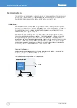
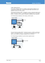
The third option provides two USB 1.1 host ports on socket
. The CSI uses ten of the twelve GPIOs. In this option, socket J12 is
not populated, and only two GPIOs are available for application use on socket J21.
The following diagram illustrates the third volume production option.
CSI with 2 GPIOs
J21
Graphics ClientM
PXA320
Processor
J4
USB 1.1 Host 1
USB 1.1 Host 2
Serial Ports
The PXA320 includes three serial ports which are available externally on the GCM. The
following table describes these serial interfaces.
Serial Header
Description
Standard
Option
1
EIA-232, 9-wire
J22: GPIO and Serial 1 (EIA-422/485)
EIA422/485
2
EIA-232, 5-wire 3.3V, 5-wire
3
EIA-232, 5-wire 3.3V, 5-wire
Serial 1 interfaces to the PXA320 full-function UART supplying the full complement of
modem control signals. This port is available at EIA-232 levels on header J15 or at
EIA422/485 levels on header J22. The processor selects the mode of operation using a
control signal mapped to GPIO97. For further details, see
Serial 2 interfaces to the PXA320 IrDA UART. A standard GCM supports a 5-wire
interface at EIA-232 levels. A 3.3 V logic level volume production option supporting an
off-board IrDA transceiver is available. This option includes an additional 3.3 V logic level
enable signal and 3.3 V output.
Serial 3 interfaces to the PXA320 Bluetooth UART signals providing a 5-wire interface. A
standard GCM supports EIA-232 levels, while a 3.3 V logic level volume production
option supporting an off-board Bluetooth transceiver is available. This option includes an
additional 3.3 V logic level enable signal and 3.3 V output.
Summary of Contents for PXA320
Page 62: ...www eurotech com ...


