background image


www.EUROPOWERgenerators.com 

EP10000E-EP12000TE-IP54-EP13500TE-EP12000E-EP16000TE-

EP14000E-EP18000TE 

Pg. 10 / 13    
Doc.nr.:0004598 


Opsteller: MH 

Revisie:02 

Revisor: BL 

Opsteldatum: 15/04/2020 

Goedkeurder: GD 

Revisiedatum: 28/06/2021 

5.7. Maintenance (see also chapter 10): 


All maintenance points (air cleaner, oil level dipstick, oil drain 
bolt, oil filler cap, oil filter, fuel filter, valves, spark plugs) are 
very good accessible. For normal maintenance activities, check the 
engine manual. For engine or alternator repair, consult your dealer. 

 
5.8. Safety for the users: 

 
The standard version of the generating sets EP10000E 

 EP12000TE-IP54 - 

EP13500TE - EP12000E - EP16000TE - EP14000E 

 EP18000TE are connected 

following the IU electrical scheme. This means that for connection of 
charges class 1 (charges with earth) there is a maximum of 1 charge 
only, and for charges class 2 (charges with double insulation, to be 

recognized by the “double square” pictogram on the machine) there is no 

limitation in the quantity of charges connected at the same time on the 
generating set. Contact your distributor for details on the above 
subject. 
 
Still you have to respect the minimum square (mm²) and maximum length 
of the cables you are using (to assure the correct switching off of the 
thermal-magnetic protection in case of short-circuit). 
Insulation protection or earth leakage protection are available as an 
option.  

 
Table: of minimum cable section (in mm²) and maximum cable length (in 
m) in function of the current (in A) 


Cable length 

Cable length 

Cable length 

Current in A 

0 to 50 metres 

> 50 to 100 

metres 

> 100 to 150 

metres 

1.5mm² 

1.5mm² 

2.5mm² 

1.5mm² 

2.5mm² 

4mm² 

10 

2.5mm² 

4mm² 

6mm² 

12 

2.5mm² 

6mm² 

10mm² 

16 

2.5mm² 

10mm² 

10mm² 

18 

4mm² 

10mm² 

10mm² 

24 

4mm² 

10mm² 

16mm² 

26 

6mm² 

16mm² 

16mm² 

36 

6mm² 

25mm² 

25mm² 

50 

10mm² 

25mm² 

35mm² 


6. INCORPORATION OF THE GENERATING SET 

 
Consult your EUROPOWER dealer or EUROPOWER Generators.  
 

See the “Mounting instructions” to be found with “Declaration of 
Incorporation according to 2006/42/EG” for generating sets that do not have 

the EC Declaration of Conformity IIA. 


Summary of Contents for EP10000E H/MA

Page 1: ...4 H So EP12000TE IP54 H GTS EP13500TE H S EP12000E H S EP16000TE H S EP14000E H S EP18000TE H S Content 0 INTRODUCTION 1 SAFETY INSTRUCTIONS 2 CE MARK NOISE LABEL AND PICTOGRAMS 3 SHORT DESCRIPTION OF...

Page 2: ...use at least 1m away from buildings or other equipments Keep children and pets away from the generator when it is in operation Gasoline is extremely flammable and explosive under certain conditions Re...

Page 3: ...to touch the muffler while it is still hot Let the engine cool down before storing the generator indoors To prevent scalding pay attention to the warning marks attached to the generator Keep in mind...

Page 4: ...e pictograms are typical for a certain option or special type of generating set Therefore not all pictograms necessarily appear on the standard generating set EP_B 1 Here you can fill the tank with fu...

Page 5: ...nnected Follow the instructions in this manual concerning the use of an earth pin 22 WARNING Hot surface Can cause burns Hot engine and hot exhaust system can cause serious and even lethal injuries Ne...

Page 6: ...st has to be installed in such a way that the object will be lifted perpendicular If that is not possible the necessary precautions must be taken to prevent load swinging e g by using two hoists each...

Page 7: ...ing to 2006 42 EG The main components of the generating set are GX630 GX690 iGX800 air cooled gasoline engine 3000rpm with starting control panel the alternator the alternator control panel the fuel t...

Page 8: ...y for EP12000E EP16000TE EP14000E and EP18000TE first put the starting key in the position ON initiation injection system only for EP14000E and EP18000TE start the engine with the starting key close t...

Page 9: ...0 to 200W is connected it will return to its nominal speed 3000rpm Note it can happen that the A I S function does not react on some small electronic charges When this occurs turn off the A I S system...

Page 10: ...quare pictogram on the machine there is no limitation in the quantity of charges connected at the same time on the generating set Contact your distributor for details on the above subject Still you ha...

Page 11: ...o alternator EP16000TE 217000118 FT2MGS 18kVA 230 400V Sincro alternator EP18000TE 217714139 SSG132LA2 R IP54 AVR 12kVA 230 400V SAEJ609B 3000tpm EP12000TE IP54 So 218000112 DWG 12 5 6 2EE IP54 12 5 6...

Page 12: ...FT with 2 diode bridges 398000630 air cleaner element GX630 GX690 iGX800 398200630 oil filter GX630 GX690 iGX800 399000030 condensator 30 F EP12000E 399000035 condensator 35 F EP12000E A00002000 spark...

Page 13: ...ehicle avoid a place exposed to direct sunlight When the generator is left in an enclosed vehicle for a longer period of time high temperature inside the vehicle could cause fuel to vaporise resulting...

Page 14: ......

Page 15: ......

Page 16: ......

Page 17: ......

Page 18: ......

Page 19: ......

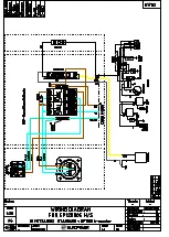
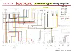
Page 20: ...ttr io 9 lii r 2 INDICATOR IGN colL 1 S PLUG 1 BATTERY STARTER FUSE l54 o SB LG _ P GR BE COLOR COMB RA r w L REG RECT R B Y B I I I I I I I Only on engine with SV on control box Only on engine with O...

Reviews: