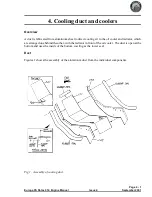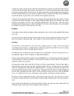
Check the fit of the duct in between the footwells, and if necessary adjust the width of the duct, then
rivet the CD1, CD2 and CD3 sections together using TAPD46BS rivets.
Rivet sealing strip to the bottom sides of the duct using TAPD46BS rivets with EUR011 load
spreading washers to prevent the rivets pulling through the sealing material.
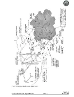
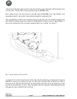
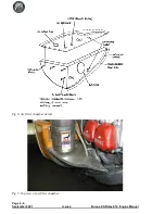
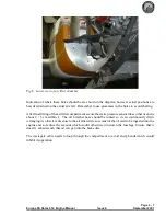
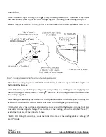
The assembled duct is fitted to the footwell using three bolts each side. The height and angle of the
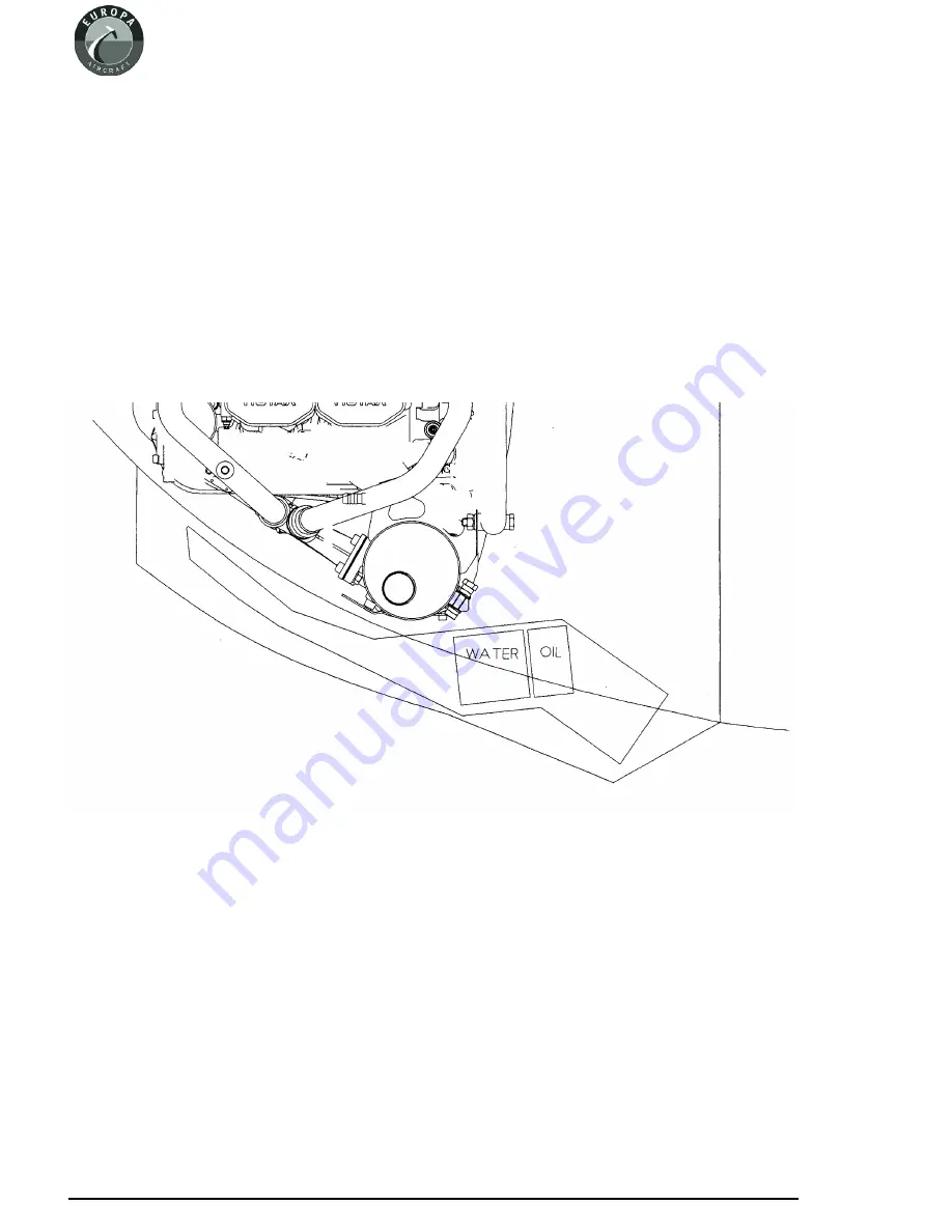
duct should be arranged to provide a clearance underneath the exhaust silencer of approximately 5
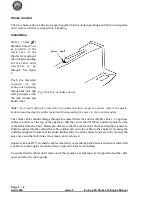
mm, and be arranged to fit the air intake opening in the lower cowling. See figure 2.
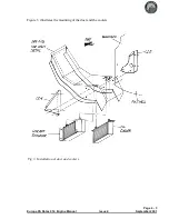
A single AN3-5A bolt screws the side of the duct onto the inside face of the footwell using an
MS21047-3 anchor nut, installed in reverse into the footwell using TAPK 36 BS rivets to make it
nearly flush; the brackets CD4 and CD5 are then bolted to the duct and to the front faces of the
footwell, again using AN3-5A bolts - these should have AN970-3 washers to spread the load into the
fibreglass structure, and MS21042-3 stiffnuts.
Page 4 - 2
June 2004
Issue 7
Europa XS Rotax 914 Engine Manual
Fig 2. Approximate position of duct.
Summary of Contents for Rotax 914
Page 14: ...INTENTIONALLY BLANK Page 2 6 November 2007 Issue 10 Europa XS Rotax 914 Engine Manual ...
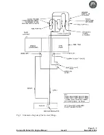
Page 28: ...Page 5 4 November 2004 Issue 8 Europa XS Rotax 914 Engine Manual Fig 2 Fuel system ...
Page 32: ...INTENTIONALLY BLANK Page 6 4 November 2004 Issue 8 Europa XS Rotax 914 Engine Manual ...
Page 40: ...INTENTIONALLY BLANK Page 8 6 September 2002 Issue 5 Europa XS Rotax 914 Engine Manual ...
Page 44: ...INTENTIONALLY BLANK Page 9 4 September 2002 Issue 5 Europa XS Rotax 914 Engine Manual ...

