background image


00079729.DOC, Version 1.0 

20/27

The operator has to make sure that safety-relating and machine-technical installations are approved by an 
expert before taking into operation for the first time and after changes before taking into operation another 
time. 
 
The operator has to make sure that safety-relating and machine-technical installations are approved by an 
expert after every four year in the course of an acceptance test. 
 
The operator has to make sure that safety-relating and machine-technical installations are approved by a 
skilled person once a year. 
 

Procedure: 

The device should be installed outside areas where persons may walk by or be seated. 
 
IMPORTANT! OVERHEAD RIGGING REQUIRES EXTENSIVE EXPERIENCE, including (but not limited to) 
calculating working load limits, installation material being used, and periodic safety inspection of all 
installation material and the device. If you lack these qualifications, do not attempt the installation yourself, 
but instead use a professional structural rigger. Improper installation can result in bodily injury and or 
damage to property. 

 
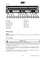
The device has to be installed out of the reach of people. 
 
If the device shall be lowered from the ceiling or high joists, 
professional trussing systems have to be used. The device must 
never be fixed swinging freely in the room. 
 

Caution:

 Devices in hanging installations may cause severe 

injuries when crashing down! If you have doubts concerning the 
safety of a possible installation, do NOT install the device! 
 
Before rigging make sure that the installation area can hold a 
minimum point load of 10 times the device's weight. 


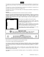
DANGER OF FIRE!

When installing the device, make sure there is no highly-inflammable
material (decoration articles, etc.) within a distance of min. 0.5 m.


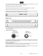
CAUTION! 

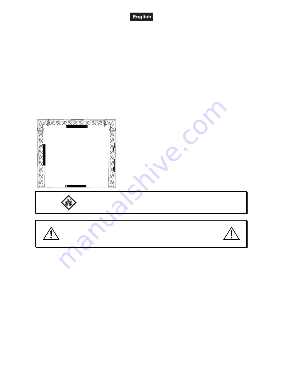
Use 2 appropriate clamps to rig the fixture on the truss. 

Make sure that the device is fixed properly! Ensure that 

the structure (truss) to which you are attaching the fixtures is secure. 

 
Mount the device to your trussing system using two appropriate clamps. 
 
For overhead use, always install an appropriate safety bond. 
 
You must only use safety bonds and quick links complying with DIN 56927, shackles complying with DIN EN 
1677-1 and BGV C1 carbines. The safety bonds, quick links, shackles and the carbines must be sufficiently 
dimensioned and used correctly in accordance with the latest industrial safety regulations (e. g. BGV C1, 
BGI 810-3). 
 

Please note:

 for overhead rigging in public or industrial areas, a series of safety instructions have to be 

followed that this manual can only give in part. The operator must therefore inform himself on the current 
safety instructions and consider them. 
 
The manufacturer cannot be made liable for damages caused by incorrect installations or insufficient safety 
precautions! 
 

Summary of Contents for LED BBS-5 Bar

Page 1: ... Copyright Nachdruck verboten Reproduction prohibited Für weiteren Gebrauch aufbewahren Keep this manual for future needs BEDIENUNGSANLEITUNG USER MANUAL LED BBS 5 Bar ...

Page 2: ...6 SAFETY INSTRUCTIONS 16 OPERATING DETERMINATIONS 17 DESCRIPTION OF THE DEVICE 18 Features 18 Overview 19 INSTALLATION 19 Rigging 19 Overhead rigging 19 DMX512 control 21 Master Slave operation 22 Connection with the mains 22 Connection between devices 22 OPERATION 23 Control Board 23 DMX controlled operation 24 Addressing 24 DMX protocol 25 CLEANING AND MAINTENANCE 26 Replacing the fuse 26 TECHNI...

Page 3: ...eachten sind wir sicher dass Sie lange Zeit Freude an Ihrem Kauf haben werden Nehmen Sie die LED BBS 5 Leiste aus der Verpackung SICHERHEITSHINWEISE ACHTUNG Seien Sie besonders vorsichtig beim Umgang mit gefährlicher Netzspannung Bei die ser Spannung können Sie einen lebensgefährlichen elektrischen Schlag erhalten Dieses Gerät hat das Werk in sicherheitstechnisch einwandfreiem Zustand verlassen Um...

Page 4: ...Netzleitung gelten auch für evtl Verlängerungsleitungen Gerät bei Nichtbenutzung und vor jeder Reinigung vom Netz trennen Fassen Sie dazu den Netzstecker an der Grifffläche an und ziehen Sie niemals an der Netzleitung Ansonsten kann das Kabel und der Stecker beschädigt werden was zu tödlichen Stromschlägen führen kann Sind Stecker oder Geräteschalter z B durch Einbau nicht erreichbar so muss netzs...

Page 5: ... NN betrieben werden Verwenden Sie das Gerät nicht bei Gewitter Überspannung könnte das Gerät zerstören Das Gerät bei Gewitter allpolig vom Netz trennen Netzstecker ziehen Das Bildzeichen m bezeichnet den Mindestabstand zu beleuchteten Gegenständen Der Abstand zwischen Lichtaustritt und der zu beleuchteten Fläche darf 0 1 Meter nicht unterschreiten Das Gerät darf nur über den Montagebügel installi...

Page 6: ...autes Mikrofon Mikrofonempfindlichkeit über das Control Board einstellbar DMX gesteuerter Betrieb oder Standalone Betrieb mit Master Slave Funktion möglich Komfortable Adressierung und Einstellung über Control Board mit vier Bedientasten und LED Anzeige mit vierstelliger 14 Segmentanzeige Schaltnetzteiltechnologie für Netzspannung zwischen 100 und 240 Volt Netzanschluss über Neutrik PowerCon Buchs...

Page 7: ...richtungen mindestens alle vier Jahre durch einen Sachverständigen im Umfang der Abnahmeprüfung geprüft werden Der Unternehmer hat dafür zu sorgen dass sicherheitstechnische und maschinentechnische Einrichtungen mindestens einmal jährlich durch einen Sachkundigen geprüft werden Vorgehensweise Das Gerät sollte idealerweise außerhalb des Aufenthaltsbereiches von Personen installiert werden WICHTIG Ü...

Page 8: ...hier nur auszugsweise wiedergegeben werden können Der Betreiber muss sich selbständig um die Beschaffung der geltenden Sicherheitsvorschriften bemühen und diese einhalten Der Hersteller haftet nicht für Schäden die durch unsachgemäße Installation und unzureichende Sicher heitsvorkehrungen verursacht werden Hängen Sie das Sicherheitsfangseil an dem dafür vorgesehenen Loch im Bodenblech ein und führ...

Page 9: ...n Verbinden Sie immer einen Ausgang mit dem Eingang des nächsten Gerätes bis alle Geräte ange schlossen sind Achtung Am letzten Gerät muss das DMX Kabel durch einen Abschlusswiderstand abgeschlossen werden Dazu wird ein XLR Stecker in den DMX Ausgang am letzten Gerät gesteckt bei dem zwischen Signal und Signal ein 120 Widerstand eingelötet ist Master Slave Betrieb Im Master Slave Betrieb lassen si...

Page 10: ...st mit einer verriegelbaren Netzanschlussbuchse ausgestattet Schließen Sie das Netzkabel an und drehen Sie es nach rechts bis es einrastet Stecken Sie den Netzstecker in eine geerdete Schutzkontaktsteckdose ein Anschluss zwischen Geräten An der Rückseite der Geräte befindet sich eine Einbaubuchse Power Out Verbinden Sie den Ausgang mit dem Netzanschluss des nächsten Gerätes bis alle Geräte angesch...

Page 11: ...wert 100 2 P P 0 P 1 P 2 P 3 P 4 P 5 Interne Programme Master Modus 3 S S 1 S 1 0 0 Gewünschte Geschwindigkeit einstellen S001 S100 zunehmend Vorgabewert 100 4 S n d S n d Musikgesteuerter Modus Master Modus 5 S e n S u 0 u 1 0 0 Mikrofonempfindlichkeit u000 u100 zunehmend Vorgabewert 80 6 U W 0 2 5 5 Dimmerintensität W000 W255 zunehmend Vorgabewerte 255 7 E n c d O N O F F Automatische TILT Kalib...

Page 12: ...berlappen damit die LED BBS 5 Leiste korrekt und unabhängig von anderen Geräten in der DMX Kette funktioniert Werden mehrere LED BBS 5 Leisten auf eine Adresse definiert arbeiten sie synchron Drücken Sie die MODE Taste um in den gewünschten DMX Modus zu gelangen und das Display d001 d512 anzeigt Über die UP oder DOWN Taste können Sie die gewünschte Adresse eingeben Drücken Sie die ENTER Taste zur ...

Page 13: ... Zunehmende Geschwindigkeit 5 6 10 Vertikale Bewegung TILT 0 255 00 FF 0 100 F Wenn Sie den Regler verschieben bewegen Sie den Kopf vertikal TILT Allmähliches Einstellen des Kopfes bei langsamen Schieben des Reglers 0 255 128 Mitte Der Kopf kann an jeder gewünschten Einstellung angehalten werden 6 7 11 Geschwindigkeit TILT Bewegung 0 255 00 FF 0 100 F Abnehmende Geschwindigkeit 7 8 12 Dimmergeschw...

Page 14: ...lmäßig von Verunreinigungen wie Staub usw gereinigt werden Verwenden Sie zur Reinigung ein fusselfreies angefeuchtetes Tuch Auf keinen Fall Alkohol oder irgendwelche Lösungsmittel zur Reinigung verwenden Im Geräteinneren befinden sich außer der Sicherung keine zu wartenden Teile Wartungs und Service arbeiten sind ausschließlich dem autorisierten Fachhandel vorbehalten Sicherungswechsel Wenn die Fe...

Page 15: ...p 7 W weiß Anzahl der LEDs 5 Max Kippbewegung TILT 240 Abstrahlwinkel 2 Maße LxBxH 663 x 80 x 143 mm Gewicht 5 10 kg Maximale Umgebungstemperatur Ta 45 C Maximale Leuchtentemperatur im Beharrungszustand TC 65 C Mindestabstand zu entflammbaren Oberflächen 0 5 m Mindestabstand zum angestrahlten Objekt 0 1 m Sicherung T 2 A 250 V Bitte beachten Sie Technische Änderungen ohne vorherige Ankündigung und...

Page 16: ...r SAFETY INSTRUCTIONS CAUTION Be careful with your operations With a dangerous voltage you can suffer a dangerous electric shock when touching the wires This device has left our premises in absolutely perfect condition In order to maintain this condition and to ensure a safe operation it is absolutely necessary for the user to follow the safety instructions and warning notes written in this user m...

Page 17: ...st can reduce the insulation which may lead to mortal electrical shock More severe dirt in and at the device should only be removed by a specialist There must never enter any liquid into power outlets extension cords or any holes in the housing of the device If you suppose that also a minimal amount of liquid may have entered the device it must immediately be disconnected This is also valid if the...

Page 18: ...Most damages are the result of unprofessional operation Never use solvents or aggressive detergents in order to clean the device Rather use a soft and damp cloth Please use the original packaging if the device is to be transported Make sure that you pack the device in the original state Please consider that unauthorized modifications on the device are forbidden due to safety reasons If this device...

Page 19: ...he respective national standards during the installation The installation must only be carried out by an authorized dealer The installation of the device has to be built and constructed in a way that it can hold 10 times the weight for 1 hour without any harming deformation The installation must always be secured with a secondary safety attachment e g an appropriate catch net This secondary safety...

Page 20: ...winging freely in the room Caution Devices in hanging installations may cause severe injuries when crashing down If you have doubts concerning the safety of a possible installation do NOT install the device Before rigging make sure that the installation area can hold a minimum point load of 10 times the device s weight DANGER OF FIRE When installing the device make sure there is no highly inflamma...

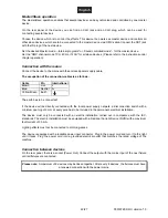
Page 21: ...tact with each other otherwise the devices will not work at all or will not work properly Please note the starting address depends upon which controller is being used Only use a DMX cable and 3 pin XLR plugs and connectors in order to connect the controller with the fixture or one fixture with another Occupation of the XLR connection If you are using controllers with this occupation you can connec...

Page 22: ...ernational Brown Live L Blue Neutral N Yellow Green Earth The earth has to be connected If the device will be directly connected with the local power supply network a disconnection switch with a minimum opening of 3 mm at every pole has to be included in the permanent electrical installation The device must only be connected with an electric installation carried out in compliance with the IEC stan...

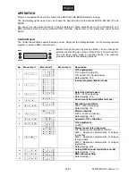
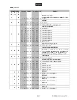
Page 23: ... level 2 Menu level 3 Description 1 t t 0 5 0 5 1 t 1 0 0 TILT angle speed TILT angle 0 50 0 240 TILT speed 51 100 increasing Default setting 100 2 P P 0 P 1 P 2 P 3 P 4 P 5 Internal programs Master mode 3 S S 1 S 1 0 0 Select the desired speed S001 S100 increasing Default setting 100 4 S n d S n d Sound controlled mode Master mode 5 S e n S u 0 u 1 0 0 Microphone sensitivity u000 u100 increasing ...

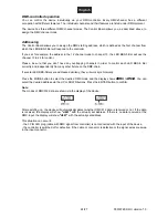
Page 24: ...ntrol each LED BBS 5 Bar correctly and independently from any other fixture on the DMX chain If several LED BBS 5 Bars are addressed similarly they will work synchronically Press the MODE button to select the desired DMX mode and the display shows d001 d512 You can select the desired address via the UP or DOWN buttons Press the ENTER button to confirm Note The modes of DMX512 data are shown via th...

Page 25: ...ternal programs 0 255 00 FF 0 100 F Increasing speed 5 6 10 Vertical movement TILT 0 255 00 FF 0 100 F Push slider up in order to move the head vertically TILT Gradual head adjustment from one end of the slider to the other 0 255 128 center The head can be stopped at any position you wish 6 7 11 TILT speed 0 255 00 FF 0 100 F Decreasing speed 7 8 12 Dimmer speed step response 0 51 00 33 0 20 S Con...

Page 26: ...installer and any safety problems have to be removed Disconnect from mains before starting maintenance operation DANGER TO LIFE We recommend a frequent cleaning of the device Please use a soft lint free and moistened cloth Never use alcohol or solvents There are no serviceable parts inside the device except for the fuse Maintenance and service operations are only to be carried out by authorized de...

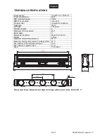
Page 27: ...e Flash rate 30 Hz LED type 7 W white Number of LEDs 5 Maximum TILT movement 240 Beam angle 2 Dimensions LxWxH 663 x 80 x 143 mm Weight 5 10 kg Maximum ambient temperature Ta 45 C Maximum housing temperature TC steady state 65 C Min distance from flammable surfaces 0 5 m Min distance to lighted object 0 1 m Fuse T 2 A 250 V Please note Every information is subject to change without prior notice 30...

Reviews: