EUROCOM D220S Service Manual Download Page 92

Schematic  Diagrams

DDR SDRAM DIMM 1 & DIMM2 (71-M2200-D06) B - 11
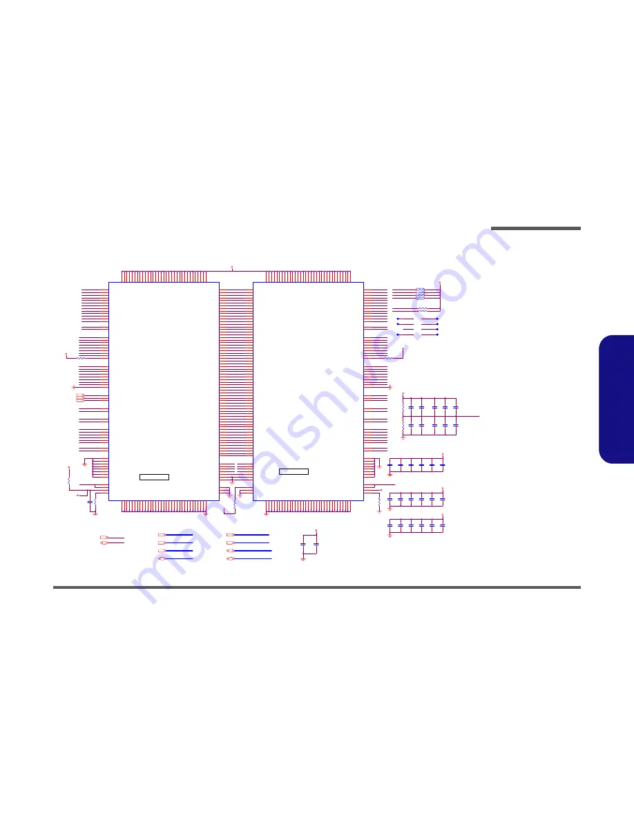
Schematic Diagrams

DDR SDRAM DIMM 1 & DIMM2 

VDDSPD

+2.5V

+3VS

+2.5V

+2.5V

+2.5V

+2.5V

+2.5V

+2.5V

+2.5V

VDDSPD

VDDSPD

+2.5V

/RCS-[0..5]

[5,9]

/RDQM[0..7]

[5,9]

/RMA[0..14]

[5,9]

/RDQS[0..7]

[5,9]

/RSWE-

[5,9]

/RSCAS-

[5,9]

/RSRAS-

[5,9]

SMBDAT

[3,12,20]

SMBCLK

[3,12,20]

DDRCLK[0..5]

[3]

CKE[0..5]

[5]

DDRCLK-[0..5]

[3]

/RMD[0..63]

[5,9]

/RDQM3

/RDQM4

/RDQM2

/RMA7

/RMA14

/RDQS7

/RDQS5

/RDQM0

/RMA3

SMBDAT

/RDQM1

/RMA12

/RMA0

DDRCLK2

/RMA1

SMBCLK

/RCS-0

/RMA11

/RMA9

/RDQS6

DDRCLK-0

/RMA6

/RDQS3

/RDQS0

/RDQM5

/RDQM7

CKE1

CKE0

/RMA10

/RMA2

/RMA8

/RDQM6

/RMA5

/RDQS2

/RDQS1

DDRCLK1

/RCS-1

DDRCLK0

/RDQS4

DDRCLK-2

DDRCLK-1

/RMA13

/RMA4

/RDQS[0..7]

/RCS-[0..5]

CKE0

CKE2

CKE3

CKE4

CKE1

/RDQM[0..7]

/RMA[0..14]

Z1002

Z1001

/RMD55

/RMD19

/RMD5

/RMD3

/RMA7

/RCS-2

/RDQM7

/RMA11

DDRCLK5

/RDQS0

/RDQM6

/RDQM0

DDRST

/RMD54

/RMD35

/RMD29

/RMD17

/RMA5

/RMA2

SMBDAT

/RDQS6

/RDQM1

/RMD60

/RMD53

/RMD36

/RMA0

DDRCLK4

/RCS-3

/RMD51

/RMD20

/RMA14

/RDQM3

/RMD40

/RMD32

DDRCLK-5

DDRCLK-4

/RDQS4

/RMD42

/RMD28

/RMD25

/RMD21

/RMD18

DDRVREF

DDRCLK-3

/RDQS7

/RDQS3

/RDQS1

/RMD47

/RMD41

/RMD34

/RMD24

/RMA9

DDRVREF

DDRCLK3

/RSRAS-

/RDQM5

/RMD61

/RMD48

/RMD44

/RMD0

/RMA12

/RMA4

/RMD37

/RMD26

/RMD15

/RMD8

/RMD6

/RMA6

DDRVREF

SMBCLK

/RMD57

/RMD38

/RDQS5

/RMD50

/RMD39

/RMD23

/RMD9

/RMD7

/RMD2

/RMA10

/RMA8

/RMA3

/RSCAS-

/RDQM2

/RMD46

/RMD31

/RMD11

/RMD1

/RMA1

CKE3

CKE2

/RDQS2

/RDQM4

/RMD30

/RMD16

/RMD12

/RMA13

/RSWE-

/RMD56

/RMD49

/RMD43

/RMD22

/RMD10

/RMD62

/RMD58

/RMD27

/RMD52

/RMD45

/RMD33

/RMD14

/RMD13

/RMD4

Z1004

/RSRAS-

/RSCAS-

/RSWE-

Z1003

Z1005

TZ1005

TZ1001
TZ1002

TZ1003

TZ1004

TZ1006

TZ1007

TZ1008

/RMD59

/RMD63

VDDSPD

CKE5

SMBDAT

SMBCLK

TZ1005

TZ1001

TZ1002

TZ1003

TZ1004

TZ1006

TZ1007

TZ1008

CKE[0..5]

DDRCLK-[0..5]

/RMD[0..63]

DDRCLK[0..5]

C611

0.01UF

C610

0.01UF

C612

0.1UF

C596

0.01UF

C594

0.01UF

C269

0.1UF

RP21

8P4RX470

8

1

7

2

6

5

3

4

C241

0.1UF

C482

0.1UF

C255

0.1UF

C484

0.1UF

C252

0.1UF

C253

0.1UF

C483

0.1UF

C595

0.1UF

C282

0.1UF

C274

0.1UF

C278

0.1UF

C277

0.1UF

C273

0.1UF

C481

0.1UF

C249

0.1UF

C251

0.1UF

U19

DDR SO-DIMM

112
111

110

109
108

107

106

105
102

101

115
100

99

117

116

5
7

13

17
6

8

14

18
19

23

29
31

20

24
30

32

41
43

49

53

42
44

50

54
55

59

65
67

56

60

66
68

127

129
135

139

128
130

136

140

141
145

151

153
142

146

152
154

163

165

171
175

164

166
172

176

177
181

187

189

178
182

188

190

9 10 21 22

33 34 36 45

46 57 58 69

70 81 82 92

93 94 113 114

131 132 143

144 155 156 157

167 168 179 180

191 192

3 4 15 16

27 28 38 39

40 51 52 63

64 75 76 87

88 90 103 104

125 126 137

138 149 150 159

161 162 173 174

185 186

85
123

124

200

86
97

98

194

196
198

1

2

197
199

71

73

79
83

72

74

80
84

12

26

48
62

134

148
170

184

78

11

25
47

61

133
147

169

183

77

118
119

120

121

122

96

95

35

160

89

37

158

91

193
195

A0
A1

A2

A3
A4

A5

A6

A7
A8

A9

A10/AP
A11

A12

BA0

BA1

DQ0
DQ1

DQ2

DQ3
DQ4

DQ5

DQ6

DQ7
DQ8

DQ9

DQ10
DQ11

DQ12

DQ13
DQ14

DQ15

DQ16

DQ17
DQ18

DQ19

DQ20
DQ21

DQ22

DQ23
DQ24

DQ25

DQ26

DQ27
DQ28

DQ29

DQ30
DQ31

DQ32

DQ33
DQ34

DQ35

DQ36
DQ37

DQ38

DQ39

DQ40
DQ41

DQ42

DQ43
DQ44

DQ45

DQ46
DQ47

DQ48

DQ49

DQ50
DQ51

DQ52

DQ53
DQ54

DQ55

DQ56
DQ57

DQ58

DQ59

DQ60
DQ61

DQ62

DQ63

VDD VDD VDD VDD

VDD VDD VDD VDD

VDD VDD VDD VDD

VDD VDD VDD VDD

VDD VDD VDD VDD

VDD VDD VDD VDD

VDD VDD VDD VDD

VDD VDD VDD

VDD VDD

VSS VSS VSS VSS

VSS VSS VSS VSS

VSS VSS VSS VSS

VSS VSS VSS VSS

VSS VSS VSS VSS

VSS VSS VSS VSS

VSS VSS VSS VSS

VSS VSS VSS

VSS VSS

DU
DU

DU

DU

DU/RESET#

DU/A13

DU/BA2

SA0

SA1
SA2

VREF

VREF

VDDSPD
VDDID

CB0

CB1

CB2
CB3

CB4

CB5

CB6
CB7

DM0

DM1

DM2
DM3

DM4

DM5
DM6

DM7

DM8

DQS0

DQS1
DQS2

DQS3

DQS4
DQS5

DQS6

DQS7
DQS8

RAS#
WE#

CAS#

S0#

S1#

CKE0

CKE1

CK0

CK1

CK2

CK0#

CK1#

CK2#

SDA
SCL

R193

8.2K

U23

DDR SO-DIMM_R

112
111

110

109
108

107

106

105
102

101

115
100

99

117

116

5
7

13

17

6

8

14

18
19

23

29
31

20

24
30

32

41
43

49

53

42
44

50

54
55

59

65
67

56

60

66
68

127

129
135

139

128
130

136

140

141
145

151

153
142

146

152
154

163

165

171
175

164

166
172

176

177
181

187

189

178
182

188

190

9

10

21

22

33

34

36

45

46

57

58

69

70

81

82

92

93

94

113

114

131

132

143

144

155

156

157

167

168

179

180

191

192

3

4

15

16

27

28

38

39

40

51

52

63

64

75

76

87

88

90

103

104

125

126

137

138

149

150

159

161

162

173

174

185

186

85

123

124

200

86
97

98

194

196
198

1

2

197
199

71

73

79
83

72

74

80
84

12

26

48
62

134

148
170

184

78

11

25
47

61

133
147

169

183
77

118
119

120

121

122

96

95

35

160

89

37

158

91

193
195

A0
A1

A2

A3
A4

A5

A6

A7
A8

A9

A10/AP

A11

A12

BA0

BA1

DQ0
DQ1

DQ2

DQ3
DQ4

DQ5

DQ6

DQ7
DQ8

DQ9

DQ10
DQ11

DQ12

DQ13
DQ14

DQ15

DQ16

DQ17
DQ18

DQ19

DQ20
DQ21

DQ22

DQ23
DQ24

DQ25

DQ26

DQ27
DQ28

DQ29

DQ30
DQ31

DQ32

DQ33
DQ34

DQ35

DQ36
DQ37

DQ38

DQ39

DQ40
DQ41

DQ42

DQ43
DQ44

DQ45

DQ46
DQ47

DQ48

DQ49

DQ50
DQ51

DQ52

DQ53
DQ54

DQ55

DQ56
DQ57

DQ58

DQ59

DQ60
DQ61

DQ62

DQ63

VDD

VDD

VDD

VDD

VDD

VDD

VDD

VDD

VDD

VDD

VDD

VDD

VDD

VDD

VDD

VDD

VDD

VDD

VDD

VDD

VDD

VDD

VDD

VDD

VDD

VDD

VDD

VDD

VDD

VDD

VDD

VDD

VDD

VSS

VSS

VSS

VSS

VSS

VSS

VSS

VSS

VSS

VSS

VSS

VSS

VSS

VSS

VSS

VSS

VSS

VSS

VSS

VSS

VSS

VSS

VSS

VSS

VSS

VSS

VSS

VSS

VSS

VSS

VSS

VSS

VSS

DU
DU

DU

DU

DU/RESET#
DU/A13

DU/BA2

SA0

SA1
SA2

VREF

VREF

VDDSPD

VDDID

CB0

CB1

CB2
CB3

CB4

CB5

CB6
CB7

DM0

DM1

DM2
DM3

DM4

DM5
DM6

DM7

DM8

DQS0

DQS1
DQS2

DQS3

DQS4
DQS5

DQS6

DQS7
DQS8

RAS#

WE#

CAS#

S0#

S1#

CKE0

CKE1

CK0

CK1

CK2

CK0#

CK1#

CK2#

SDA
SCL

R164

8.2K

R172

470

R422

75 1%

R434

75 1%

R187

10K

R171

470

R188

0

R366

10K

C279

0.1UF

C280

0.1UF

C281

0.1UF

R362

1K

C270

10U/16V

C271

10U/16V

T166

T169

T170

T167

T163

T172

T173

C728

0.1UF

C727

0.1UF

C730

0.1UF

C729

0.1UF

addr =1010000b

addr =1010001b

DIMM

DECOUPLING

DDRVREF GEN. & DECOUPLING

Sheet 10 of 31

DDR SDRAM 

DIMM1 & DIMM2

Summary of Contents for D220S

Page 1: ......

Page 2: ...Preface I Preface Notebook Computer M220S M270S D220S D270S Service Manual...

Page 3: ...in part be reproduced translated transmitted or reduced to any machine readable form without prior consent from the vendor manufacturer or creators of this publica tion except for copies kept by the...

Page 4: ...up basic information for servicing and or upgrading components of the notebook PC The following information is included Chapter 1 Introduction provides general information about the location of syste...

Page 5: ...manual for additional information User s Manual on CD This describes the notebook PC s features and the procedures for operating the computer and its ROM based setup pro gram It also describes the in...

Page 6: ...isplay 1 3 LCD 1 3 Storage 1 4 Audio 1 4 Interface 1 5 Communication 1 5 Power Management 1 5 Power 1 6 Indicators 1 6 Environmental Spec 1 6 Physical Dimensions 1 6 Weight 1 6 Optional 1 6 External L...

Page 7: ...Battery 2 6 Removing the System Memory 2 7 Removing the Keyboard 2 8 Removing the Hard Disk Drive 2 9 Removing the CPU 2 10 Removing the Modem 2 12 Removing the CD Device 2 12 Removing the Bottom Case...

Page 8: ...Floppy Disk Drive D220S A 19 Hard Disk Drive D220S A 20 Top M270S A 21 Bottom M270S A 22 LCD 14 M270S A 23 CD ROM Drive QSI M270S A 24 CD RW Drive Toshiba M270S A 25 Combo Drive QSI M270S A 26 DVD ROM...

Page 9: ...DDR SSTL 2 Termination Resistors B 12 LVDS Interface SiS301 2LV B 13 961A 1 PCI IDE HyperZip 1 of 4 B 14 961A 2 Misc Signals 2 of 4 B 15 961A 3 USB 3 of 4 B 16 961A 4 Power RTC 4 of 4 B 17 IDE LVDS I...

Page 10: ...Preface IX Preface Inverter Board B 32...

Page 11: ...Preface X Preface...

Page 12: ...computer Operating systems e g DOS Windows 9x Windows 2000 Windows XP etc have their own manuals as do application software e g word processing and database programs If you have questions about those...

Page 13: ...ocess Technology 256KB L2 Cache 400MHz FSB 2 0 GHz Mobile Model Mobile Intel Pentium 4 Processor 478 pin Micro FCPGA package 0 13 0 13 Micron Process Technology 512KB L2 Cache 400MHz FSB 1 4 2 2 GHz M...

Page 14: ...ACPI 1 0B Display UMA Architecture with 16 32 64 MB System Memory sharable as Display Memory UltraAGP Integrated 128 bit 2D 3D graphics engine Motion compensation and IDCT accelerator for DVD content...

Page 15: ...2 5 9 5 12 7mm HDD Supports UDMA mode 2 Supports PIO mode 4 Supports ATA 33 ATA 66 ATA 100 Audio AC 97 2 1 compliant interface Compatible with Sound Blaster PRO 16 Advanced Wavetable Synthesizer Dire...

Page 16: ...mouse PS 2 type port One speaker out headphone out jack One microphone in or S PDIF output jack for Y cable One RJ 11 jack for modem One RJ 45 jack for 100M 10M LAN One DC in jack Communication 10 100...

Page 17: ...k Caps Lock Scroll Lock AC Battery Icon Environmental Spec Temperature Relative Humidity Operating 5 C 35 C Operating 20 80 Non Operating 20 C 60 CNon Operating 10 90 Physical Dimensions 308 w x 254 d...

Page 18: ...ernal Locator Top Views 11 2 5 6 7 8 9 4 8 3 10 1 Figure 1 Top Views 1 LCD Panel 2 Microphone built in 3 Close Cover Switch 4 LED Status Indicators 5 Hot Key Buttons 6 Power Button 7 Keyboard 8 Speake...

Page 19: ...View Left Side View Figure 2 Right Side View 1 Security Lock Slot 2 Vent 3 CD Device Figure 3 Left Side View 1 S PDIF Out Port Microphone In Jack 2 Headphone Out Jack 3 Volume Control Knob 4 PC Card...

Page 20: ...Bottom Views Figure 4 Rear View 1 DC In Jack 2 PS 2 Type Port 3 Parallel Port 4 RJ 11 Phone Jack 5 Vent 6 External Monitor CRT Port 7 Dual USB Ports 8 S Video Port 9 IEEE 1394 Port 10 RJ 45 LAN Jack...

Page 21: ...oard Overview Top Key Parts 1 CPU Socket no CPU Installed 2 Northbridge SiS 650 3 SiS 301 LVDS Interface 4 TSB41AB21 1394 PHY IEEE1394 Con troller 5 RTL8100BL LAN Controller 6 ALC201 AC 97 Audio Codec...

Page 22: ...troduction Mainboard Overview Bottom Key Parts Figure 7 Mainboard Overview Bottom Key Parts 1 Super I O Con troller 2 Southbridge SiS 961 3 PCMCIA 4 LAN Transformer 5 Flash BIOS ROM 6 2 DIMM Sockets 7...

Page 23: ...ble Connectors Switches 1 CN16 Micro phone Cable 2 CN15 LCD Cable 3 CN14 Inverter Cable 4 CN11 CPU Fan Cable 5 CN12 CPU Fan Cable 6 CN13 Modem Cable 7 CN17 HDD Con nector 8 CN18 Keyboard Connector 9 C...

Page 24: ...oduction Mainboard Overview Bottom 1 13 1 Introduction Mainboard Overview Bottom Cable Connectors and Switches Figure 9 Mainboard Bottom Cable Connectors Switches 1 PCMCIA Module 2 Battery Connec tor...

Page 25: ...Introduction 1 14 1 Introduction...

Page 26: ...each section may have a box in the page margin Information contained under the figure will give a synopsis of the sequence of procedures involved in the disassembly procedure A box with a lists the r...

Page 27: ...ing the connection make sure the connector is oriented in the same way The pin1 side is usually not indicated Pressure sockets for multi wire connectors To release this connector type grasp it at its...

Page 28: ...Do not pull on the wire 6 Peripherals Turn off and detach any peripherals 7 Beware of static discharge ICs such as the CPU and main support chips are vulnerable to static electricity Before handling...

Page 29: ...ove the battery page 2 6 2 Remove the keyboard page 2 8 3 Remove the CPU page 2 10 To remove the Modem 1 Remove the battery page 2 6 2 Remove the keyboard page 2 8 3 Remove the modem page 2 12 To remo...

Page 30: ...e the Inverter 1 Remove the battery page 2 6 2 Remove the keyboard page 2 8 3 Remove the HDD page 2 9 4 Remove the CPU page 2 10 5 Remove the modem page 2 12 6 Remove the CD device page 2 12 7 Remove...

Page 31: ...2 Remove screws in Figure 2 1a and release the battery cover 3 Separate the battery connector from the computer and pull the battery out Figure 2 1 Battery Removal Sequence a Remove the two screws an...

Page 32: ...l pop up and you can remove it 5 Insert a new module holding it at about a 30 angle and fit the connectors firmly into the memory slot Figure 2 2 MemoryRemoval Sequence a Remove the screw then remove...

Page 33: ...out being careful not to bend the keyboard ribbon cable Figure 2 3b 4 Disconnect the keyboard ribbon cable from the locking collar socket Figure 2 3b Figure 2 3 Keyboard Removal Sequence a Press the f...

Page 34: ...e case and disconnect the HDD connector board 5 Just reverse the removal procedure to install the new HDD 12 HDD 13 HDD case 14 HDD connector Board 9 Screws Figure 2 4 Hard Disk Removal Sequence a Rem...

Page 35: ...5 Processor Removal Sequence Remove the four screws from the heat sink in the or der indicated 5 1 4 5 5 1 3 2 4 1 3 2 4 Caution The heat sink and CPU area in general contains parts which are subject...

Page 36: ...igure 2 6b to unlock the CPU 5 Carefully it may be hot lift the CPU up out of the socket Figure 2 6c 6 When re inserting the CPU pay careful attention to the pin alignment it will fit only one way don...

Page 37: ...evice 1 Turn the computer OFF remove the battery page 2 6 and keyboard page 2 8 2 Remove screw and apply gentle but firm pressure at point to slide the CD device out of the computer Figure 2 8 3 Modem...

Page 38: ...ry page 2 6 keyboard page 2 8 hard disk assembly page 2 9 CPU page 2 10 and CD device page 2 12 2 Turn the computer over and remove screws Figure 2 9 5 Heat Sink 4 Screws Figure 2 9 Bottom Case Remova...

Page 39: ...6 Disconnect the inverter cable LCD cable and microphone cable Figure 2 11b 7 Carefully lift the LCD and top case assembly off the bottom case assembly 1 Figure 2 10 Bottom Case Removal Sequence Cont...

Page 40: ...m page 2 12 CD device page 2 12 and bottom case page 2 13 2 Remove screw and hex nut from the FDD assembly 3 Carefully disconnect the FDD cable and lift the FDD assembly off the mainboard Figure 2 12...

Page 41: ...ge 2 12 CD device page 2 12 bottom case page 2 13 and FDD assembly page 2 15 2 Remove screws and hex nut 3 Lift the mainboard out of the bottom case Figure 2 13 5 Mainboard 6 Bottom case 3 Screws 1 He...

Page 42: ...ddle of the frame to carefully unsnap the LCD front panel module from the back 4 Remove screws from the inverter and disconnect cables from the rear of the inverter 5 Lift the inverter off the LCD ass...

Page 43: ...ly lift the LCD panel off the top assembly Figure 2 15a 3 Disconnect the LCD cable from the LCD connector Figure 2 15b 4 Remove screws and separate the LCD panel from the brackets Figure 2 15c 9 LCD P...

Page 44: ...r organization may use a different system so be sure to cross check any relevant documentation Note Some assemblies may have parts in common especially screws However the part lists DO NOT indicate th...

Page 45: ...age A 12 page A 21 page A 30 Bottom page A 4 page A 13 page A 22 page A 31 LCD 14 page A 5 page A 14 page A 23 page A 32 CD ROM Drive page A 6 page A 15 page A 24 page A 33 CD RW Drive Toshiba page A...

Page 46: ...Part Lists Top M220S A 3 Part Lists Top M220S Figure 1 Top M220S...

Page 47: ...Part Lists A 4 Bottom M220S Part Lists Bottom M220S Figure 2 Bottom M220S...

Page 48: ...Part Lists LCD 14 M220S A 5 Part Lists LCD 14 M220S Figure 3 LCD 14 M220S...

Page 49: ...Part Lists A 6 CD ROM Drive Toshiba M220S Part Lists CD ROM Drive Toshiba M220S Figure 4 CD ROM Drive M220S...

Page 50: ...Part Lists CD RW Drive Toshiba M220S A 7 Part Lists CD RW Drive Toshiba M220S Figure 5 CD RW Drive M220S...

Page 51: ...Part Lists A 8 Combo Drive QSI M220S Part Lists Combo Drive QSI M220S Figure 6 Combo Drive M220S...

Page 52: ...Part Lists DVD ROM Drive QSI M220S A 9 Part Lists DVD ROM Drive QSI M220S Figure 7 DVD ROM Drive M220S...

Page 53: ...Part Lists A 10 Floppy Disk Drive M220S Part Lists Floppy Disk Drive M220S Figure 8 Floppy Disk Drive M220S...

Page 54: ...Part Lists Hard Disk Drive M220S A 11 Part Lists Hard Disk Drive M220S Figure 9 HDD Drive M220S...

Page 55: ...Part Lists A 12 Top D220S Part Lists Top D220S Figure 1 Top D220S...

Page 56: ...Part Lists Bottom D220S A 13 Part Lists Bottom D220S Figure 2 Bottom D220S...

Page 57: ...Part Lists A 14 LCD 14 D220S Part Lists LCD 14 D220S Figure 3 LCD 14 D220S...

Page 58: ...Part Lists CD ROM Drive Toshiba D220S A 15 Part Lists CD ROM Drive Toshiba D220S Figure 4 CD ROM Drive D220S...

Page 59: ...Part Lists A 16 CD RW Drive Toshiba D220S Part Lists CD RW Drive Toshiba D220S Figure 5 CD RW Drive D220S...

Page 60: ...Part Lists Combo Drive QSI D220S A 17 Part Lists Combo Drive QSI D220S Figure 6 Combo Drive D220S...

Page 61: ...Part Lists A 18 DVD ROM Drive QSI D220S Part Lists DVD ROM Drive QSI D220S Figure 7 DVD ROM Drive D220S...

Page 62: ...Part Lists Floppy Disk Drive D220S A 19 Part Lists Floppy Disk Drive D220S Figure 8 Floppy Disk Drive D220S...

Page 63: ...Part Lists A 20 Hard Disk Drive D220S Part Lists Hard Disk Drive D220S Figure 9 HDD Drive D220S...

Page 64: ...Part Lists Top M270S A 21 Part Lists Top M270S Figure 1 Top M270S...

Page 65: ...Part Lists A 22 Bottom M270S Part Lists Bottom M270S Figure 2 Bottom M270S...

Page 66: ...Part Lists LCD 14 M270S A 23 Part Lists LCD 14 M270S Figure 3 LCD 14 M270S...

Page 67: ...Part Lists A 24 CD ROM Drive QSI M270S Part Lists CD ROM Drive QSI M270S Figure 4 CD ROM Drive M270S...

Page 68: ...Part Lists CD RW Drive Toshiba M270S A 25 Part Lists CD RW Drive Toshiba M270S Figure 5 CD RW Drive M270S...

Page 69: ...Part Lists A 26 Combo Drive QSI M270S Part Lists Combo Drive QSI M270S Figure 6 Combo Drive M270S...

Page 70: ...Part Lists DVD ROM Drive QSI M270S A 27 Part Lists DVD ROM Drive QSI M270S Figure 7 DVD ROM Drive M270S...

Page 71: ...Part Lists A 28 Floppy Disk Drive M270S Part Lists Floppy Disk Drive M270S Figure 8 Floppy Disk Drive M270S...

Page 72: ...Part Lists Hard Disk Drive M270S A 29 Part Lists Hard Disk Drive M270S Figure 9 HDD Drive M270S...

Page 73: ...Part Lists A 30 Top D270S Part Lists Top D270S Figure 1 Top D270S...

Page 74: ...Part Lists Bottom D270S A 31 Part Lists Bottom D270S Figure 2 Bottom D270S...

Page 75: ...Part Lists A 32 LCD 14 D270S Part Lists LCD 14 D270S Figure 3 LCD 14 D270S...

Page 76: ...Part Lists CD ROM Drive QSI D270S A 33 Part Lists CD ROM Drive QSI D270S Figure 4 CD ROM Drive D270S...

Page 77: ...Part Lists A 34 CD RW Drive Toshiba D270S Part Lists CD RW Drive Toshiba D270S Figure 5 CD RW Drive D270S...

Page 78: ...Part Lists Combo Drive QSI D270S A 35 Part Lists Combo Drive QSI D270S Figure 6 Combo Drive D270S...

Page 79: ...Part Lists A 36 DVD ROM Drive QSI D270S Part Lists DVD ROM Drive QSI D270S Figure 7 DVD ROM Drive D270S...

Page 80: ...Part Lists Floppy Disk Drive D270S A 37 Part Lists Floppy Disk Drive D270S Figure 8 Floppy Disk Drive D270S...

Page 81: ...Part Lists A 38 Hard Disk Drive D270S Part Lists Hard Disk Drive D270S Figure 9 HDD Drive D270S...

Page 82: ...5 CPU Socket 478 1 of 2 Page B 4 961A 2 Misc Signals 2 of 4 Page B 15 CPU VCORE Page B 26 CPU Socket 478 2 of 2 Page B 5 961A 3 USB 3 of 4 Page B 16 System Power 1 SCH 3V 5V 12V Page B 27 Clock Genera...

Page 83: ...T PORT IR PORT GTL AGTL 2149 MEMORY CONTROL 702 PIN BGA 1 8V CORE WITH MIXED 1 2V 1 5V 2 5V 3 3V I 0 371 PIN BGA 3 3V I 0 1 8V CORE WITH MIXED 1 2V 1 5V 2 5V MIC IN PORT Analog Out PORT 4MB ROM XBUS R...

Page 84: ...V SB1 8V 2 5VDIMM or VCC3MEM PWRTN PSON MAIN POWERS VCC5 VCC3 3 VCC2 5V VCC1 8V VCCVID DDR_VTT CORE_ON VCC_CORE PWRGD TO CHIP PCIRST DEVICE SIS650 VGA CHRONTEL CH0717 LAN REL8139C CB TI 1410A 1394 TI...

Page 85: ...Y21 AA25 AA22 AA24 K2 K4 L6 K1 L3 M6 L2 M3 M4 N1 M1 N2 N4 N5 T1 R2 P3 P4 R3 T2 U1 P6 U3 T4 V2 R6 W1 T5 U4 V3 W2 Y1 AB1 AD24 AB4 AA5 Y6 AC4 AB5 AC6 H3 J3 J4 K5 J1 AC24 AC23 AB22 AC21 F4 G5 F1 U6 W4 Y3...

Page 86: ...2 51 1 1 R234 82_1 R305 82_1 RP35 4P2RX0 R 1 2 3 4 T149 T148 JCPU1B NORTHWOOD478 AC1 V5 A5 AC26 AD26 AE25 L5 R5 P1 E5 D1 F6 F20 AA6 AA21 W23 P23 J23 F21 W22 R22 K22 E22 AF23 AF22 AC3 V6 B6 Y4 AA3 W5 A...

Page 87: ...21 1 2 C586 0 1UF C621 0 1UF C603 10PF R C573 10UF 16V C524 10PF R C532 10PF R C589 10UF 16V C619 10UF 16V C531 10PF R C605 0 1UF C602 0 01UF C533 0 1UF C618 10UF 16V C620 0 01UF C591 0 1UF C502 10PF...

Page 88: ...R221 0 R R223 0 R R24 0 R69 22 R R28 20 1 R17 120_1 R29 113 1 R15 150 1 C86 0603 R R76 8 2K R47 22 R R224 22 R38 22 R23 22 R251 22 R54 22 T44 T114 R222 0 U6A SIS650 AJ26 AH26 U24 U26 V26 C20 D19 T27 U...

Page 89: ...121 1 2 N11 N10 C132 0 1UF C131 0 01UF C177 0 01UF C176 0 01UF C180 0 01UF C179 0 01UF C178 10PF R L33 BK1608HS121 1 2 R282 4 7K R118 22 R119 150 1 R120 150 1 C449 10UF 16V C138 0 01UF C139 0 1UF C424...

Page 90: ...15 10UF 16V R1 130 1 R22 4 7K R3 4 7K R263 56 R68 150 1 R72 150 1 R4 33 R5 33 T132 T13 T118 T24 T125 T129 T5 T135 D3 BAV99 C AC A R9 4 7K R R11 4 7K R R10 100 R8 100 T11 T140 C450 10UF 16V C115 0 1UF...

Page 91: ...A20 A22 A24 A26 C19 C21 C23 C25 C27 E20 E22 E24 F25 H25 K25 M25 P25 T25 V25 Y25 AB25 AD25 E27 G27 J27 L27 N27 R27 U27 W27 AA27 AC27 AE27 D29 F29 H29 K29 M29 P29 T29 V29 Y29 AB29 AD29 AF29 AE24 AG25 B...

Page 92: ...A6 A7 A8 A9 A10 AP A11 A12 BA0 BA1 DQ0 DQ1 DQ2 DQ3 DQ4 DQ5 DQ6 DQ7 DQ8 DQ9 DQ10 DQ11 DQ12 DQ13 DQ14 DQ15 DQ16 DQ17 DQ18 DQ19 DQ20 DQ21 DQ22 DQ23 DQ24 DQ25 DQ26 DQ27 DQ28 DQ29 DQ30 DQ31 DQ32 DQ33 DQ34...

Page 93: ...1UF C285 0 1UF C516 0 1UF C557 0 1UF C568 0 1UF C563 0 1UF C554 0 1UF C291 0 1UF C287 0 1UF C283 0 1UF C553 0 1UF C292 0 1UF C566 0 1UF C561 0 1UF C555 0 1UF C569 0 1UF C565 0 1UF C560 0 1UF C507 0 1U...

Page 94: ...6 97 98 99 100 101 102 103 104 105 106 107 108 109 110 111 112 113 114 115 116 117 118 119 120 121 122 123 124 125 126 127 128 LVDSPLLVDD LPLL RESERVED LPLLCA LVDSPLLVSS LPLL LAVSS LGND RESERVED LL2C...

Page 95: ...1405 SZCMP_P SVSSZCMP RESETOUT PCIRST RESETOUT PCIRST SZ4XAVSS REQ2 PLOCK T76 T180 T177 R345 0 L67 BK1608HS121 1 2 RP71 8P4RX4 7K 8 1 7 2 6 5 3 4 RP55 10P8RX2 7K 10 9 8 7 6 1 2 3 4 5 RP74 8P4RX2 2K 8...

Page 96: ...D31 1N4148 A C RP77 10P8RX10K 10 9 8 7 6 1 2 3 4 5 Y7 32 768KHZ 1 2 R435 10M R489 4 7K R475 100K R474 100K R448 4 7K R423 0 R512 4 7K R426 4 7k R471 4 7K R467 4 7K R357 4 7K R469 10K R470 10K RP78 10...

Page 97: ...15 G18 G19 G20 G17 J16 H17 H16 G16 D16 F17 D17 E17 B17 E19 B19 F19 B16 A17 F16 A18 C15 C16 C17 B20 F20 D20 E20 C20 A20 A19 C19 A12 B12 C12 D12 E12 A13 B13 C13 D11 C11 E11 A10 B10 A11 E10 D9 B11 C9 C10...

Page 98: ...C206 10UF 16V Q6 MMBT3906 B E C R320 10K R169 1K D8 1N4148 A C C599 0 01UF JBAT1 CON2 1 2 1 2 U25D SIS961 G15 J15 J17 L15 L17 N15 P17 K15 G6 H15 L6 M15 R6 R10 R14 P15 R15 H6 K6 M6 P6 R7 R9 R11 R13 J6...

Page 99: ...11 IDEDB12 2IDB12 IDEDB13 2IDB13 2IDB8 2IDB9 IDEDB10 2IDB11 IDEDB8 IDEDB9 IDERST Z1805 Z1804 PCICLKDEBUG TRDY IRDY FRAME PCIRST Z990 LDC0 LDC2 LDC1 LDC1 LDC0 LDC2 LL1C BAT_LED POWER_ON TP_CLK TP_DATA...

Page 100: ...A C D7 F01J2E A C Q4 2SB1198K C150 10U 1206 T T T T R79 10 R C148 10U 1206 T C347 0 1UF R T T C27 1000P 2KV 1206 R209 75 C74 27P T U2 H0009 1 2 3 8 6 7 16 11 15 9 14 10 4 5 12 13 RX RX RXC TX TXC TX R...

Page 101: ...12 CCBE2 A7 CAD18 A6 CAD20 A5 CAD21 A4 CAD22 A3 CAD23 A2 CAD24 A1 CAD25 A0 CAD26 D0 CAD27 D1 CAD29 D2 RFU WP IOIS16 CKRUN GND GND GND GND GND GND GND GND GND GND CD1 CCD1 D11 CAD2 D12 CAD4 D13 CAD6 D1...

Page 102: ...2 24 576MHZ 1 2 R74 0 R TSB43AB21 POWER CLASS OSCILLATOR PHY PORT 2 BIAS CURRENT FILTER PHY PORT 1 EEPROM 2 WIRE BUS PCI BUS INTERFACE U4 13 16 18 19 21 22 24 25 26 28 29 31 32 36 37 38 40 41 42 43 45...

Page 103: ...6 7 8 CP4 8P4C 1 2 3 4 5 6 7 8 LP1 BK32164S471 1 2 3 4 5 6 7 8 LP4 BK32164S471 1 2 3 4 5 6 7 8 LP2 BK32164S471 1 2 3 4 5 6 7 8 L46 FCM1608K 601 1 2 LP3 BK32164S471 1 2 3 4 5 6 7 8 RP79 10P8RX8 2K R 1...

Page 104: ...C16 270PF C523 2200PF C313 4 7UF C221 0 1UF C478 0 1UF C477 0 1UF C222 22PF C223 22PF C238 0 1UF C231 10UF 16V C473 4 7UF C242 0 1UF C582 1UF C233 0 1UF C219 100PF C220 100PF C218 100PF R331 100 R297...

Page 105: ...UF C175 10U C170 0 1UF C160 10U R C230 0 1UF U11 ALC201A 12 18 19 20 26 42 25 38 7 4 9 1 28 27 11 10 8 6 5 2 3 33 34 39 40 41 43 44 45 46 47 48 37 29 30 31 32 22 23 24 13 14 15 16 17 21 35 36 PC_BEEP...

Page 106: ...TOOTH_EN Z2421 Z2424 Z2425 Z2419 AC_SDIN1 AC_BITCLK AC_SYNC Z2426 Z2422 Z2423 LID_RSUM GATE_LID_SW R440 10K R R458 10K L78 BK1608HS121 R L77 BK1608HS121R C625 47PF R L53 BK2125HS121 1 2 D9 RB751V A C...

Page 107: ...2 0 PR67 10 PQ19 2N7002 G D S PR66 22K PR1 2m 2512 PD9 RB751V A C PC48 0 1UF PR68 10 PC77 330P PR2 2m 2512 PQ18 2N7002 G D S PL3 1UH PC9 220U PR39 237K_1 PC75 1000P PR14 0 R PC18 220U PR65 10K PC55 0...

Page 108: ...1M PQ5B FDS6982S 7 2 1 8 PR122 10 PR120 0 PR135 0 PR134 0 PR136 0 R PR133 R R PR118 10K PR121 0 PR125 2M PR131 10 7K_1 PR130 10K_1 PL7 CDRH 1205 100 PR4 12m 2512 PC39 10U 25V_O PC34 220U PC40 10U 25V...

Page 109: ...20K_1 PR32 11K_1 PC21 220U PC24 220U PR9 12m 2512 PR11 20m 1206 PR16 10 PR17 0 PR24 0 PR76 1M PQ24 2N7002 G D S PQ23 2N7002 G D S PQ22 2N7002 G D S PR75 100K PQ25 2N7002 G D S PR78 100K PR74 0 PJ4 6mm...

Page 110: ...2 G D S U21F 74LVC14 13 12 14 7 U21E 74LVC14 11 10 14 7 T T Q24 2SJ360 G D S T PQ39 2N7002 G D S PQ38 2N7002 G D S PR114 100K PR115 10K PR116 20K PC103 1U R PR107 10K PD20 1N4148 A C PD21 1N4148 A C P...

Page 111: ...1205 470 PD3 03A04 C A PD4 03A04 C A PC82 0 1UF PC81 0 1UF PC93 1U PU6 TL594 1 2 3 4 5 6 7 8 9 10 11 12 13 14 15 16 1IN 1IN FBK DTC CT RT GND C1 E1 E2 C2 VCC OUT REF 2IN 2IN PD18 1SS355 A C PU2A LM358...

Page 112: ...1 H12 HoleC237D107A 2 3 4 5 6 7 8 9 1 H8 HoleC237D107A 2 3 4 5 6 7 8 9 1 H9 HoleC237D107B 2 3 4 5 6 7 8 9 1 H20 HoleC217D110 2 3 4 5 6 7 8 9 1 H16 HoleC217D110 2 3 4 5 6 7 8 9 SS1 Hole197D91 1 H29 Hol...

Page 113: ...R11 470K 1 1 2 C10 0 1uF X7R 1 2 C12 10nF X7R 1 2 R15 300K 1 2 C2 1uF 1 2 U1 MP1015 11 12 13 14 15 16 17 18 19 20 10 9 4 7 1 2 3 5 6 8 BtR PGnd_R OutR BATT0 REF COMP FT VLSB ISFB AGND BtL PGnd_L DBRT...

Reviews: