background image

www.euroboor.com 


Table of contents 

Table of contents .............................................................................................................. 3


1. Safety ........................................................................................................................... 4


1.1 General safety instructions .............................................................................................. 4


1.2 Specific safety information ............................................................................................... 8


2. Description ................................................................................................................. 10


2.1 intended use ................................................................................................................... 10


2.2 Description and features ................................................................................................ 11


2.3 Box contents ................................................................................................................... 12


2.4 Serial number ................................................................................................................. 12


2.5 Technical data ................................................................................................................ 13


2.6 Symbols .......................................................................................................................... 14


2.7 Environmental ................................................................................................................ 15


3. Preparation & adjustment ........................................................................................... 16


3.1 Assembly ........................................................................................................................ 16


3.2 Prior to use ..................................................................................................................... 16


3.3 Fitting the blade ............................................................................................................. 18


3.4 Replacing the blade ........................................................................................................ 19


3.5 Setting cutting angle ....................................................................................................... 21


3.6 Clamping the workpiece ................................................................................................. 22


3.7 Adjusting cutting depth .................................................................................................. 24


4. Using the machine ...................................................................................................... 25


4.1 Turning the motor on and off......................................................................................... 25


4.2 Restart mid-cut ............................................................................................................... 26


4.3 Carrying the machine ..................................................................................................... 26


5. Maintenance ............................................................................................................... 27


6. Troubleshooting .......................................................................................................... 29


7. Exploded view & Partslist ............................................................................................ 30


7.1 Exploded view ................................................................................................................ 30


7.2 Spare parts list ................................................................................................................ 32


8. Warranty and service .................................................................................................. 35


9. Certifications............................................................................................................... 36


9.1 CE declaration of conformity.......................................................................................... 36


9.2 Intertek proof of certification ........................................................................................ 37


Summary of Contents for EDC.355

Page 1: ...Operators manual V 1 0 EN April 2022 Dry Cut Off Metal Saw 14 355 mm EDC 355 ...

Page 2: ...ative portable tools that add value for our customers and facilitate them in their daily work We never lose sight of sustainability time savings and cost savings Enjoy your new machine Before operating your dry cutting machine please read all instructions first These include the Operators Manual and warning label on the unit itself With proper use car and maintenance your model will provide you wi...

Page 3: ...ent 16 3 1 Assembly 16 3 2 Prior to use 16 3 3 Fitting the blade 18 3 4 Replacing the blade 19 3 5 Setting cutting angle 21 3 6 Clamping the workpiece 22 3 7 Adjusting cutting depth 24 4 Using the machine 25 4 1 Turning the motor on and off 25 4 2 Restart mid cut 26 4 3 Carrying the machine 26 5 Maintenance 27 6 Troubleshooting 29 7 Exploded view Partslist 30 7 1 Exploded view 30 7 2 Spare parts l...

Page 4: ...n electric shock fire and or serious injury SAVE ALL WARNINGS AND INSTRUCTIONS FOR FUTURE REFERENCE This Operator s Manual including the General Safety Instructions should be kept for later use and enclosed with the power tool should it be passed on or sold The term power tool in the warnings refers to your mains operated corded power tool Please also observe the relevant national industrial safet...

Page 5: ...dy contact with grounded surfaces such as pipes radiators ranges and refrigerators There is an increased risk of electric shock if your body is earthed or grounded 3 Do not expose power tools to rain or wet conditions Water entering a power tool will increase the risk of electric shock 4 Do not abuse the cord Never use the cord to carry the power tool or pull the plug from an outlet Keep cord away...

Page 6: ...t overreach Keep proper footing and balance at all times This enables better control of the power tool in unexpected situations 6 Dress properly Do not wear loose clothing or jewellery Keep your hair clothing and gloves away from moving parts Loose clothes jewellery or long hair can be caught in moving parts 7 If devices are provided for the connection of dust extraction and collection facilities ...

Page 7: ...those intended could result in a hazardous situation 9 Use only accessories that are recommended by EUROBOOR for your power tool Accessories that may be suitable for one machine may become hazardous when used on another power tool SERVICE 1 Power tool service must be performed only by qualified repair personnel Service or maintenance performed by unqualified personnel could result in risk of injur...

Page 8: ... EUROBOOR dealer and have these replaced b Always check if the blade can run freely before you start working with the machine Have the Dry Cut Off Metal Saw serviced by qualified repair personnel at your EUROBOOR dealer if the blade cannot run freely or vibrates heavily c Check the blade for cracks or other damage before operation Do not use blade when it is damaged or deformed d Check if your wor...

Page 9: ...if the blade cannot run freely or vibrates heavily 7 Do not reach behind or over the cutting tool when it is connected to the power source 8 Do not reach your hands in or near the path of the saw blade 9 Do not cut any objects that are not clamped using the clamp of the dry cutting machine 10 Do not make any adjustments to the machine removing or securing the workpiece when the blade has not come ...

Page 10: ... is 1 450 RPM with soft start The machine has an extra safety button to prevent accidental starts For cutting the machine can be adjusted from 0 to 45 corners Also the dept can be adjusted using the depth adjustment screw WARNING The machine should not be converted or modified e g for any other form of use other than as specified in these operating instructions Warranty will be voided and the user...

Page 11: ...chine EDC 355 1 Safety button 9 Aluminium base with size indication 2 On off trigger 10 Engine cover air intake 3 Hand protection shield 11 Arm lock pin 4 Retractable blade cover 12 Depth adjustment screw 5 Clamp knob 13 Angle indication 6 Spindle cover 14 Brand label 7 Dust cover 15 Sawblade 8 Dust collection tray ...

Page 12: ...ey M10 2x Spare carbon brushes 2 4 Serial number The serial number is mentioned on the machine twice on the motor and base The serial number will help you and your sales point validate and identify the machine For example 3552204001 Breaks down to 355 22 04 001 Machine Year Month Identification number Maintain labels name plates and other machine identification These carry important information Ob...

Page 13: ...power 2 480 W 11 A Speed 1 450 rpm Max blade diameter 355 mm 14 Bore diameter 25 4 mm 1 Max cutting angle 45 Voltage 230 V 50 60 Hz 120 V 60 Hz 2 5 1 Cutting capacities EDC 355 Metric Imperial Cutting capacity 0 105 x 105 mm 4 1 8 x 4 1 8 Cutting capacity 0 90 x 145 mm 3 9 16 x 5 11 16 Cutting capacity 0 120 mm 4 3 4 Cutting capacity 45 80 x 80 mm 3 1 8 x 3 1 8 Cutting capacity 45 90 x 80 mm 3 9 1...

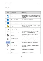
Page 14: ...n Observe the information in the adjacent text European conformity symbol Confirms the conformity of the power tool with the directives of the European Community ISO9001 Certified in accordance with ISO9001 2015 quality management system Class of protection II Product with double layered insulation In case of failure of the main layer of insulation the product remains safe due to a second layer of...

Page 15: ...of measure for the motor speed 2 7 Environmental Separate collection This product must not be disposed of with normal household waste Separate collection of used products and packaging allows materials to be recycled and used again Re use of recycled materials helps prevent environmental pollution and reduces the demand for raw materials Local regulations may provide for separate collection of ele...

Page 16: ...itched off and the power supply is disconnected 3 2 Prior to use Prior to any use check the machine and all of its components for damage and check that all moving parts are in perfect working order and do not jam All parts must be correctly installed and must fulfil all conditions necessary to ensure perfect operation of the machine A damaged and or incorrectly functioning machine must be repaired...

Page 17: ...d Earth grounding is not required If the power supply cord is damaged it must be replaced by a specially prepared cord available through the EUROBOOR service organisation EXTENSION CABLE If an extension cable is required use an approved extension cable suitable for the power input of this tool see technical data The minimum conductor size is 1 5 mm the maximum length is 30 meter When using a cable...

Page 18: ...locks in place After the spindle is locked keep the lock on and at the same time loosen the spindle bolt using the M10 hexagon key 3 When the spindle bolt is loosened remove the small flange and the front flange from the driveshaft Note Keep the back flange in place 4 Raise the retractable blade cover to its highest position While remaining in that position the sawing blade can be placed onto the ...

Page 19: ...s using the M6 hexagon key 3 4 Replacing the blade WARNING Before undertaking any type of preparation or adjustment make sure the machine is switched off and the power supply is disconnected 1 Remove the spindle cover by loosening the two bolts using the M6 hexagon key 2 Put on the spindle lock by using the spindle lock lever Carefully rotate the blade by hand until the spindle lock locks in place...

Page 20: ...ing blade can be placed onto the spindle Note Check the blade for cracks or other damage before operation Do not use blade when it is damaged or deformed Also check if the blade can run freely and without vibrating 6 Lower the retractable blade cover and put the front flange and small flange back into place 7 Tighten the spindle bolt using the M10 hexagon key Make sure the spindle is locked using ...

Page 21: ...e the screw will be loosened By lifting the angle lock lever slightly and moving it back clockwise the screw can be loosened even further 2 After loosening the angle lock screw tilt up the angle lock pin 2 turn it a quarter which locks the pin in the raised position 3 The cutting angle can be adjusted by moving the plate to the desired position 3 Use the angle indication engraved in the base for y...

Page 22: ...ick lock and release lever 1 by tilting it backwards and pull back the clamp from the plate 2 2 Place the workpiece between the plate and clamp 3 Push the clamp against the workpiece 3 4 When the clamp is against the workpiece Put the quick lock and release lever 4 back in its original position Tighten the workpiece by turning the clamp knob clockwise 5 Note For releasing the workpiece from a pres...

Page 23: ... position 1 is suitable for workpieces of maximum 150 mm position 2 is suitable for workpieces of up to 180mm Changing between these positions can be done in the following steps 1 Fully loosen all screws that lock the plate 2 After all screws are loosened completely pull out and lock the angle lock pin 3 The plate can be replaced in the other position now 4 When placed in the new position fully ti...

Page 24: ... to touch the surface under the base 3 7 1 Increase depth of cut To increase the depth of cut loosen the depth adjustment bolt by turning it counter clockwise then rotate the nut in clockwise direction until it is fully tightened 3 7 2 Reduce depth of cut To reduce the depth of cut rotate the nut in counter clockwise direction firstly then tighten the depth adjustment bolt by turning it clockwise ...

Page 25: ...eed 5 Check if the blade runs freely and is not vibrating If the blade cannot run freely or is vibrating heavily stop immediately and refer to your EUROBOOR dealer 6 Slowly lower the blade onto the workpiece and cut through firmly Do not force the machine or put too much pressure as this will only shorten the lifetime of the blade and increase wear on the machine 7 When the workpiece is finished r...

Page 26: ... When the blade is carried separately from the machine make sure the blade is in its box holder to prevent injuries from sharp edges Lock the arm in lowered position 1 Lower the machine s arm and keep it in the fully lowered position 2 While in lowered position press the lock pin The lock pin will lock the arm in lowered position 3 Now the machine is ready to be carried Carry the machine using the...

Page 27: ...ct the operation of the machine Particular notice must be taken of the mains cable switches and moving parts If the machine appears to be damaged it should not be used Failure to do so may cause injury or death CLEANING Clean all dirt dust metal chips and burrs from the machine regularly The use of compressed air is advised Never remove metal chips with bare hands Blow dirt and dust out of the mot...

Page 28: ...d with the machine to the EUROBOOR dealer for service when requesting repair or other maintenance EUROBOOR machines are constantly being improved and modified to incorporate the latest technological advancements Accordingly some parts i e part numbers and or design may be changed without prior notice Also due to EUROBOOR s continuing program of research and development the specifications of machin...

Page 29: ...r vibrations Check the positioning of the workpiece Put less pressure on the machine while cutting Retractable blade cover does not fully open or close Defective spring or connection rod Blade not fitted properly Blade not the right size too big Rough cuts Put less pressure on the machine while cutting Worn blade replace blade Not the correct blade for the application Machine vibrates or shakes Sa...

Page 30: ...www euroboor com 30 7 Exploded view Partslist 7 1 Exploded view ...

Page 31: ...www euroboor com 31 ...

Page 32: ... A 1 15 EDC355 0015 Screw ST4x16mm N A 12 16 EDC355 0016 Right handle N A 1 17 EDC355 0017 Cable guard N A 1 18 EDC355 0018EU Plug EU 220 230V N A 1 EDC355 0018USA Plug USA 110 120V EDC355 0018UK GCC Plug UK GCC 220 230V EDC355 0018UK Plug UK 110V 16A 19 EDC355 0019 Cutting arm N A 1 20 EDC355 0020 Top handle N A 1 21 EDC355 0021 Screw set M5x20mm N A 4 22 EDC355 0022 Left handle N A 1 23 EDC355 0...

Page 33: ...m 66T stainless steel 55 EDC355 0055 Hand protection shield N A 1 56 EDC355 0056 Screw M5x12mm N A 2 57 EDC355 0057 Spring washer Ø5 N A 2 58 EDC355 0058 Bolt M6x8mm N A 2 59 EDC355 0059 Spindle cover N A 1 60 EDC355 0060 Spindle bolt M10x20mm 1 61 EDC355 0061 Small flange 1 62 EDC355 0053 Blade flange 1 63 EDC355 0063 Spring for retractable blade cover 1 64 EDC355 0064 Cross screw M6 N A 2 65 EDC...

Page 34: ...EDC355 0093 Spring washer N A 1 94 EDC355 0094 Nut M8 N A 1 95 EDC355 0095 Support plate N A 1 96 EDC355 0096 Fixed support N A 1 97 EDC355 0097 Angle lock screw 1 98 EDC355 0098 Hexagon screw M10x30 1 99 EDC355 0099 Plate N A 1 100 EDC355 0100 Positioning knob 1 101 EDC355 0101 Angle lock pin 1 102 EDC355 0102 Aluminium base N A 1 103 EDC355 0103 Rubber foot N A 2 104 EDC355 0104 Hexagon screw M5...

Page 35: ...iod can be extended to 24 months in total by registering the product on our website https Euroboor com support register Service To maximise the lifetime of your EUROBOOR machine always use service and parts from an official EUROBOOR distribution channel Whenever in need of such always contact original point of sales or if no longer existent the distributor of EUROBOOR products in your country Seri...

Page 36: ...ype as brought into circulation by EUROBOOR BV Designation function Dry cut off metal sawing machine Brand EUROBOOR Types EDC 355 Ratings and principal 230 240V AC 50 60Hz Class II Characteristics Power 2 480 W 11A Speed 1 450 rpm Applicable guidelines 2006 42 EC The Machinery Directive Used standards EN 62841 1 2015 AC 15 EN 62841 3 10 2015 A11 17 Testing laboratory Intertek Zoetermeer 7 April 20...

Page 37: ...listed here reflect the status at the time of release of this certificate Date of issue 15 1 2013 Certificate type Intertek authorization mark This authorizes the application of the Certification Mark s shown below to the models described in the Product s covered section when made in accordance with the conditions set forth in the Certification Agreement and Listing report This authorization also ...

Reviews: