background image

21

2121341-06-11/20 (Translation of the original operating instructions)

Operating Instructions MODULAR SAFETY CONTROL SYSTEM MSC

MSC FIELDBUS MODULES CE-...

EN

6.  Fault diagnostics

FAULT DIAGNOSTICS

MEANING

LED

ON

GREEN

RUN

GREEN

IN FAIL

RED

EXT FAIL

RED

LED1

RED/GREEN

LED2

RED/GREEN

Internal microcontroller fault

ON

OFF

2 flashes*

OFF

See tables for the modules

Internal printed circuit board fault 

ON

OFF

3 flashes*

OFF

Configuration error

ON

OFF

5 flashes*

OFF

BUS communication error 

ON

OFF

5 flashes*

OFF

BUS communication interrupted

ON

OFF

ON

OFF

Identical module detected

ON

OFF

5 flashes*

5 flashes

* The sequence of the LED flashes is as follows: ON for 300 ms and OFF for 400 ms with an interval of 1 s between two sequences.

Table 12:  Fault diagnostics

Summary of Contents for CE Series

Page 1: ...EN Operating Instructions MODULAR SAFETY CONTROL SYSTEM MSC MSC FIELDBUS MODULES CE ...

Page 2: ... status on the SPM modules 12 5 Diagnostics 13 5 1 I O index field 13 5 2 Diagnostic code field 14 5 3 Signals and pin assignment 15 5 4 Module CANopen CE CO 15 5 5 Module DeviceNet CE DN 16 5 6 Module PROFIBUS CE PR 17 5 7 Module EtherCAT CE EC 17 5 8 Module EtherNet IP CE EI 18 5 9 Module EtherNet IP CE EI2 18 5 10 Module PROFINET CE PN 19 5 11 Module Modbus TCP IP CE MT 19 5 12 Module Modbus RT...

Page 3: ...R WARNING CAUTION Safety precautions Danger of death or severe injuries Warning about possible injuries Caution slight injuries possible NOTICE Important Notice about possible device damage Important information Tip Useful information FW 2 0 Fieldbus module firmware version 2 0 FW 2 0 Fieldbus module firmware version 2 0 1 4 Supplementary documents The overall documentation for this device consist...

Page 4: ...SC system 2 USB Mini B plug connector to the PC 3 BUS plug connector to the fieldbus not available on CE US 4 Front connection power supply Terminal block side A top Terminal Signal 1 24 VDC 20 2 3 4 GND Table 1 Terminal assignment WARNING Ì Install safety modules in a control cabinet that meets degree of protection IP54 as a minimum Ì The power supply for the modules must be 24 VDC 20 PELV as per...

Page 5: ...s Ì 64 bytes reserved for analog data that are not available in the current EUCHNER portfolio Ì 64 bytes for diagnoses FW 2 0 The output structure comprises Ì one status byte Ì a variable number of bytes for the status of the inputs max 16 bytes Ì one byte for the feedback of the fieldbus inputs Ì two bytes for the status of the fieldbus outputs Ì a variable number of bytes for the status of the s...

Page 6: ...ries in the following se quence MSC CB MSC CB S FI8FO2 AC FO2 AC FO4 AZ FO4 AZ FO4O8 AH FO4SO8 FI8FO4S If several modules of the same type are installed the order corresponds to the node number A diagnostic element consists of an index of the I O with a problem and a diagnostic code of the problem FW 2 0 The diagnostic area in the output structure comprises 64 bytes and the first 23 diagnostic ele...

Page 7: ...l operating instructions Operating Instructions MODULAR SAFETY CONTROL SYSTEM MSC MSC FIELDBUS MODULES CE EN 4 1 Input structure FW 2 0 MSC CB MSC CB S 4 bytes MSC CB S MSC CB S Figure 2 Input structure FW 2 0 The input structure size is one byte ...

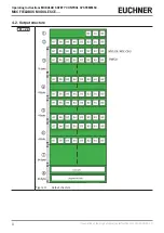
Page 8: ...perating Instructions MODULAR SAFETY CONTROL SYSTEM MSC MSC FIELDBUS MODULES CE 8 Translation of the original operating instructions 2121341 06 11 20 4 2 Output structure FW 2 0 Figure 3 Output structure ...

Page 9: ...the analog inputs 64 bytes Diagnostics 64 bytes Each input or safety output function block is linked to the diagnostic code The system exports 2 bytes on the fieldbus for every diagnosis Ì The index for the related I O Ì The diagnostic code NOTICE Refer to the Diagnostics chapter in this manual for more information about the indices of the I Os and the diagnostic codes If I O is OK the system expo...

Page 10: ...US MODULES CE 10 Translation of the original operating instructions 2121341 06 11 20 Figure 4 Bus Configurator User Interface input and output structures Key for Figure 4 Bus Configurator User Interface input and output structures see key for Figure 3 Output structure ...

Page 11: ...must be set under Settings Activation for this purpose Important The compatibility mode functions only in combination with a base unit MSC CB or with a fieldbus module with a firmware version 2 0 Figure 5 Bus Configurator User Interface compatibility mode FW 2 0 The Backward Compatibility tab appears after the compatibility mode is set see Figure 5 The I O Select area can be used to define the sub...

Page 12: ...h Proximity switch Code Meaning Code Meaning 0 Out of range counterclockwise CCW 0 Out of range 1 Within range counterclockwise CCW 1 Within range 2 Out of range clockwise CW 3 Within range clockwise CW Table 5 Speed range monitoring SPEED CONTROL Encoder encoder proximity switch Proximity switch Code Meaning Code Meaning 0 Speed limit counterclockwise CCW 0 Speed limit 1 Speed limit counterclockw...

Page 13: ...s Ì 0 as index value Ì Diagnostic code OK 0x80 If there is a problem on the I O the system sends two bytes to the fieldbus with Ì The index for the related I O Ì The relative diagnostic code 5 1 I O index field This field indicates the number of the I O with the diagnostic code that is not OK The area of the I O index depends on the base unit used The possible values are shown in Table 8 Signal ty...

Page 14: ...input is present on more than one OUT_TEST 20 Connection incorrect The test signal is present on more than one input 21 Output stuck The test signal on the input is not present on the OUT_TEST 22 Second OUT_TEST KO Redundancy check on the OUT_TEST failed 23 SPM proximity missing Proximity switch not fitted proximity switch does not work 24 SPM encoder missing Encoder not fitted encoder not supplie...

Page 15: ...4 Module CANopen CE CO DB9 male plug view on front PIN SIGNAL 1 2 CAN_L 3 CAN_GND 4 5 CAN_SHIELD 6 7 CAN_H 8 9 Housing CAN_SHIELD OPR LED STATUS INDICATION DESCRIPTION GREEN OPERATIONAL OPERATIONAL state GREEN flashing slowly PRE OPERATIONAL PRE OPERATIONAL state GREEN 1 flashing STOPPED STOPPED state GREEN flashing quickly Autobaud Baud rate detection RED EXCEPTION EXCEPTION state ERR LED STATUS ...

Page 16: ...connections made GREEN flashing 1 Hz On line not connected No connections made RED Critical connection error CE DN communication not possible RED flashing 1 Hz Timeout of 1 or more connection One or more I O devices have timed out GREEN RED alternately TEST CE DN check in progress STS LED STATUS INDICATION DESCRIPTION GREEN Normal operation GREEN flashing 1 Hz Pending Configuration incomplete CE D...

Page 17: ...STER or CE PR incorrect STS LED STATUS INDICATION DESCRIPTION OFF CE PR not initialized SETUP STATE or NW_INIT GREEN Initialized End of initialization NW_INIT GREEN flashing Initialized with diagnostic active EXTENDED DIAGNOSTIC bit set RED Exception error EXCEPTION STATE 5 7 Module EtherCAT CE EC STS LED STATUS INDICATION DESCRIPTION OFF INIT INITIALIZATION or no voltage GREEN OPERATIONAL OPERATI...

Page 18: ... OFF No power Green RUN state GREEN flashing Not configured RED Fatal error One or more unrecoverable errors detected RED flashing Error One or more recoverable errors detected 5 9 Module EtherNet IP CE EI2 NET LED STATUS INDICATION DESCRIPTION OFF No voltage or no IP address GREEN Online connected GREEN flashing Online not connected RED Duplicate IP address RED flashing Connection timeout STS LED...

Page 19: ...o flashes IP address error IP address not configured RED three flashes Configuration error Error during identification STS LED STATUS INDICATION DESCRIPTION OFF Not initialized GREEN Normal operation GREEN one flash Diagnostic event RED Exception Fatal event Module in the EXCEPTION severe internal error state in combination with RED NET 5 11 Module Modbus TCP IP CE MT NET LED STATUS INDICATION DES...

Page 20: ...COM LED STATUS INDICATION DESCRIPTION OFF No power or no data exchange YELLOW Frame reception or transmission Data exchange RED Fatal Error One or more unrecoverable errors detected STS LED STATUS INDICATION DESCRIPTION OFF Initializing or no power GREEN Module initialized RED Fatal Error One or more unrecoverable errors detected RED one flash Communication fault or configura tion error Ì Invalid ...

Page 21: ...REEN Internal microcontroller fault ON OFF 2 flashes OFF See tables for the modules Internal printed circuit board fault ON OFF 3 flashes OFF Configuration error ON OFF 5 flashes OFF BUS communication error ON OFF 5 flashes OFF BUS communication interrupted ON OFF ON OFF Identical module detected ON OFF 5 flashes 5 flashes The sequence of the LED flashes is as follows ON for 300 ms and OFF for 400...

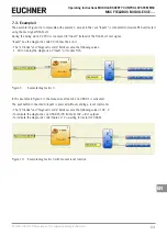
Page 22: ...signal MSC CB Test1 Ì The I O index and Diagnostic code fields assume the following values 1 20 to display the diagnosis at input 1 of the MSC CB module connection error Figure 7 Example diagnostics 1 7 2 Example 2 NOTICE The I O index corresponds to the logical block and not the terminal number on the module MSC CB In Figure 8 the two hand switching element connected to the terminals Input1 and I...

Page 23: ... diagnostic code 20 Connection error Ì The I O index and Diagnostic code fields assume the following values 1 20 to display the diagnosis at Input1 of module FI16 Figure 9 Example diagnostics 3 In this example in Figure 10 the manual reset function on OSSD 1 is activated The pushbutton connected to Input1 is pressed without sending a reset command Ì The I O index and Diagnostic code fields assume ...

Page 24: ...S MSC EUCHNER CE US MSC CONNECT ON RUN EUCHNER IN EXT COM ENA FAIL 1 2 3 4 5 MSC CB 6 7 8 1 2 1 2 1 2 OSSD CLEAR IN STATUS MSC ON IN EXT RUN EUCHNER FAIL CE PR MSC OPR ERR MSC CB bus module MSC CB CE US USB Figure 11 Connection examples It is to be noted that the behavior of BUS CONFIGURATOR changes depending on whether the communication is with a bus module or a module CE US Ì BUS MODULE THE SOFT...

Page 25: ... USB cable to the PC and the fieldbus module 3 On the desktop click the Bus Configurator User Interface icon The following configuration window appears Figure 12 Figure 12 Bus Configurator User Interface configuring fieldbus module 4 Click the Connect button The program detects that a fieldbus module is connected Figure 13 The status bar shows the fieldbus model the firmware version of the fieldbu...

Page 26: ...e by clicking the Write button ADDRESS BAUDRATE DATA SETS CE CO 127 AUTO Input status Fieldbus input status Fieldbus output status Probe Output status CE DN 63 AUTO Input status Fieldbus input status Fieldbus output status Probe Output status CE PR 126 NZ Input status Fieldbus input status Fieldbus output status Probe Output status CE EC 0 NZ Input status Fieldbus input status Fieldbus output stat...

Page 27: ...uts and outputs and the diagnoses are shown in Figure 14 and Figure 15 The first 16 diagnoses are displayed If more than 16 diagnoses are available the additional diagnoses are displayed after the preceding ones are deleted Figure 14 Input output status Figure 15 Input output diagnostics The fieldbus input with a logical status that can be changed as required by the programmer only for the module ...

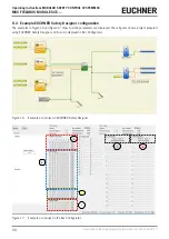
Page 28: ...xample EUCHNER Safety Designer configuration The examples in Figure 16 and Figure 17 show how the parameters are displayed These figures show a project prepared using EUCHNER Safety Designer and how it is displayed in Bus Configurator Figure 16 Example of a project in EUCHNER Safety Designer 1 6 3 4 2 5 Figure 17 Example of a project in the Bus Configurator ...

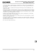
Page 29: ...corresponding status is represented by the bit pair 0 and 1 of byte 1 Input State area The diagnostic is displayed in the group box reserved for the input diagnostic where 2 is displayed in the index field and the corresponding diagnostic is displayed Ì The fieldbus outputs FIELDBUS PROBE on bits 6 and 16 are green and the corresponding bits in the Probe Status area are active Bit 8 is displayed a...

Page 30: ...Operating Instructions MODULAR SAFETY CONTROL SYSTEM MSC MSC FIELDBUS MODULES CE 30 Translation of the original operating instructions 2121341 06 11 20 ...

Page 31: ...31 2121341 06 11 20 Translation of the original operating instructions Operating Instructions MODULAR SAFETY CONTROL SYSTEM MSC MSC FIELDBUS MODULES CE EN ...

Page 32: ...Edition 2121341 06 11 20 Title Operating Instructions MODULAR SAFETY CONTROL SYSTEM MSC MSC FIELDBUS MODULES CE Translation of the original operating instructions Copyright EUCHNER GmbH Co KG 11 2020 Subject to technical modifications no responsibility is accept ed for the accuracy of this information ...

Reviews: