29
2121341-06-11/20 (Translation of the original operating instructions)
Operating Instructions MODULAR SAFETY CONTROL SYSTEM MSC
MSC FIELDBUS MODULES CE-...
EN
Ì
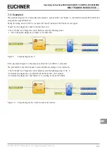
The input block1 “E-Stop” is connected to inputs 6/7, terminal K22/23, on the base unit. The corresponding status (0
or 1) is represented by bit 5 of byte 0 (“Input State” area). Bit 6 is set to 0; it is used to signal that the “E-Stop” occu-
pies two terminals.
Ì
The input block 2 “Enable” is connected to input 3, terminal K19 on the base unit. The corresponding status is repre-
sented by bit 7 of byte 0.
Ì
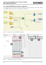
The input block 3 “Mod-Sel” is connected to the inputs 1/2, terminals K17/18 on the FI8FO2 module. Here, the diagnos-
tics indicates that MOD-SEL is not connected. The corresponding status is represented by the bit pair 0 and 1 of byte 1
(“Input State” area). The diagnostic is displayed in the group box reserved for the input diagnostic, where 2 is displayed
in the index field and the corresponding diagnostic is displayed.
Ì
The fieldbus outputs (FIELDBUS PROBE) on bits 6 and 16 are green, and the corresponding bits in the “Probe Status”
area are active. Bit 8 is displayed as bit 0 of the third byte.
Ì
Output block 1 “OSSD” is ON and connected to the first output of the base unit. The corresponding status is represent-
ed by bit 0 of byte 0 (“Output State” area).
Ì
The output block 2 “OSSD” is OFF; here, the diagnostics states that a restart is awaited. The OSSD is connected to the
first output pair of FI8FO2. The corresponding status is represented by bit 2 of byte 0. The diagnostics are displayed in
the group box reserved for diagnostics.
Ì
Bit 0 is active in the “Fieldbus Input State” area.


