Manual of Board ET-TOUCH PAD 4x4 V2
www.etteam.com
-
2
-
1
3
2
4
5
6
7
8
9
0
SHIFT
HELP
ENTER
CLEAR
1. LED-STATUS
2. TOUCH-PAD
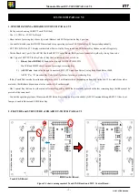
From Figure 2.1 above, it shows how to assemble Board ET-TOUCH 4x4 V2 when separated this board into 2 parts and then re-
assembled both parts together, please assemble board as shown in the figure above. While assembling both parts together, please notice
direction of the arrowhead or cut-angle PCB of MCU-Control Board, it must be the same direction as shown at the back of Touch PAD
Board; and finally, user can assembly both parts together.
Figure 2.2 shows the front of Touch PAD Board.
Figure 2.3 shows the front and the back of MCU Controller Board.
7. TTL232
6. JP-LED
5. JP-BZ
3. RS232
4. JP-232
11. LOAD-FW
8. Buzzer
10. O/P BCD Key Code
9. Con-Touch PAD1
12. Con-Touch PAD2
ต ำแหน่ง Key F


