ETS ETS.A Operating Manual Download Page 20

Manufacturer


www.ets-by.by


Distributor


www.metrotec.ee


20


7


Troubleshooting


Typical Errors and Instructions for Fixing These  

Error 

Error Description 

Instructions for Fixing 

Oscillator 

frequency 
equals 0 

Code: 1.4 V 

Description: 

oscillator  not  working,  the 

sensor does not measure fuel level. 

Explanation: 

the  error  is  either  occasional 

(parts shorted by water when in motion) or 
permanent  (in  the  case  of  mechanical 
shorting of wires or sensing tubes) character. 
When  the  cause  of  the  error  is  removed, 
normal operation resumes. 

Cause: 

shorting of the tubes of the sensing 

assembly 

– 

either there is water in the fuel 

or a mechanical short-circuit is present. 

1.


Allow  the  sensor  to  dry,  drain 

water from the tank; 
2.


Fix  the  mechanical  short-circuit. 

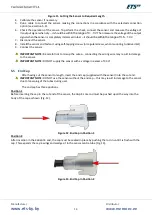
With  the  sensor  switched  off,  use  a 
tester 

to 

measure 

resistance 

between  the  tubes  of  the  sensing 
assembly.  The  measured  value 
should  be    in    the    range    of  

460…500 kΩ

EEPROM read 

error 

Code: 1.8 V 

Description: 

The  parameters  that  were  set 

when  the  sensor  was  calibrated  have 
become corrupted. 

Explanation: 

the error manifests as soon as 

the sensor is switched on and is permanent, 
i.e. the output signal value is not affected by 
immersing the sensor in fuel or by shorting 
its electrodes. 

Cause: 

possible  damage  by  static  discharge 

when cutting the sensor to length. 

1.


Short-circuit the electrodes of the 

sensing  assembly  by  means  of  a 
metallic  object.  If  this  does  not 
change  the  output  signal  of  the 
sensor,  the  sensor  is  not  functional 
and has to be replaced. 
2.


If shorting the electrodes changes 

the output signal of the sensor, either 
the  measuring  device  that  is  being 
used  has  a  fault  or  has  been 
connected  incorrectly.  Measure  the 
output  voltage  using  a  properly 
functioning  device  that  has  been 
connected correctly for  voltage 
measurement. 

Upper limit of 

range 

exceeded 

F > Fmax +10% 

Code: 2.0 V 

Description: 

at low levels, the sensor 

’sticks’ 

at zero, subsequently displaying the error. 

Explanation: 

the error is manifested when 

the sensor 

is ’dry’

. When the sensor is 

immersed in fuel and after passing the dead 
zone, normal operation resumes. 

Cause: 

the sensor has been cut by more than 

10% (for non-cuttable sensors), or by more 
than 60% (for cuttable sensors). The sensor 
has  been  incorrectly  calibrated.  Damage  to 

the sensor’s electrodes

1.  Calibrate  the  sensor.  If  this  does 
not  fix  the  problem,  contact  the 
manufacturer. 

Summary of Contents for ETS.A

Page 1: ...Fuel Level Sensor ETS A Operating Manual...

Page 2: ...Construction and Principle of Operation 4 5 Installation and Operation 6 5 1 Requirements for Use 6 5 2 Installation Basics 6 5 3 Connection Error Bookmark not defined 5 4 Installation Sequence 13 5...

Page 3: ...e signal input specifications correspond to the sensor s technical parameters Figure 1 Fuel Level Sensor ETS A To increase reliability and improve operating parameters the sensor includes the followin...

Page 4: ...exceeding 40 95 or lower Upper and lower limit values of output signal and lowest value of the signal depend on the length to which the sensor has been cut Additional limiting error accounts for the e...

Page 5: ...e code assigned to the error concerned see the table Diagnostic Codes of Sensor Errors Diagnostic Codes of Sensor Errors Code Sensor Output Voltage V Error Description 1 0 Sensor s lower and upper lim...

Page 6: ...d fuel level sensor inlet or by cutting an opening for the sensor in the tank It is recommended to install the sensor as close as possible to the geometric centre of the tank Fig 3a in order to avoid...

Page 7: ...veral sensors may be combined Fig 5 using a summator see Operating Manual for Summator ETS 3 0 IMPORTANT NOTE Where the readings of several sensors are to be combined frequency based sensors Fuel Leve...

Page 8: ...the sensor to the vehicle two versions of the sensor are manufactured Version 1 Sensor body made of aluminium Rated for sensor connection to vehicle s onboard network after the chassis ground switch...

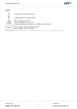
Page 9: ...Manufacturer www ets by by Distributor www metrotec ee 9 Legend...

Page 10: ...in order to ensure protection of onboard network from short circuits in the power supply of the monitoringsystem NOTE The connection to is made on an onboard power wire with the ignition off To preven...

Page 11: ...power and ground terminals on the battery IMPORTANT NOTE This connection scheme MUST NOT be used on fuel tanks of petrol enginevehicles IMPORTANT NOTE When using the scheme make sure that there is no...

Page 12: ...s of the sensor of the monitoring terminal or of any other applicable devices adding a 20 reserve Sensor supply voltage 10 33 V Sensor supply current max 20 m Figure 9 Connection Using a Supplementary...

Page 13: ...maximum prior to the drilling of any openings The fuel tank of a petrol engine MUST BE either filled with water or removed and the remaining petrol evaporated 2 Cut the sensor to required length see F...

Page 14: ...nect the sensor IMPORTANT NOTE Be careful not to mix up the wires connecting the wrong wire may result in damage to the sensor IMPORTANT NOTE DO NOT supply the sensor with a voltage in excess of 33 V...

Page 15: ...ge when dry 0 V output voltage when completely immersed 3 5 0 2 V output signal variability range 3 5 V Observe that the drop range of the output signal has been reduced by half from 6 82 to 3 5 V IMP...

Page 16: ...onfig 2 Cut the sensor to required length 3 Plug the end cap into the cut ends of the sensing tubes see section 6 3 4 Connect the sensor to PC as shown in Fig 15 Figure 15 Connecting the Sensor to PC...

Page 17: ...ed next Fig 19 indicate the connection port Press the button Connect Figure 19 Calibration Window When the sensor has been successfully connected the application will indicate the connection the main...

Page 18: ...ube Fig 22 Figure 22 Disconnecting the Probe 11 Disconnect the probe and wait until the application displays the message Done showing completion of the calibration process Fig 23 Figure 23 Completion...

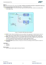
Page 19: ...Manufacturer www ets by by Distributor www metrotec ee 19 Figure 24 Voltage of Sensor When Dry...

Page 20: ...the sensor is switched on and is permanent i e the output signal value is not affected by immersing the sensor in fuel or by shorting its electrodes Cause possible damage by static discharge when cutt...

Page 21: ...it is caused by the presence of water or impurities in the fuel Cause the composition of the liquid measured differs from that of diesel or petrol Periodic shorting of the measuring element in the tan...

Page 22: ...odes Length Code 1 350 mm 2 500 mm 3 700 mm 4 1000 mm 5 1400 mm 6 265 mm 7 680 mm 8 730 mm 9 750 mm Non standard length Date sensor production date coded in UNIX time without the first and the two las...

Page 23: ...ions ambient air temperature 40 C 80 C relative humidity at 40 C 95 all covered means of transport are allowed Storage The sensor may be stored in its original packaging under the following conditions...

Page 24: ...Manufacturer www ets by by Distributor www metrotec ee 24...

Reviews: