background image

5

EtherWAN Series Router Hardware Installation Guide

Hardware

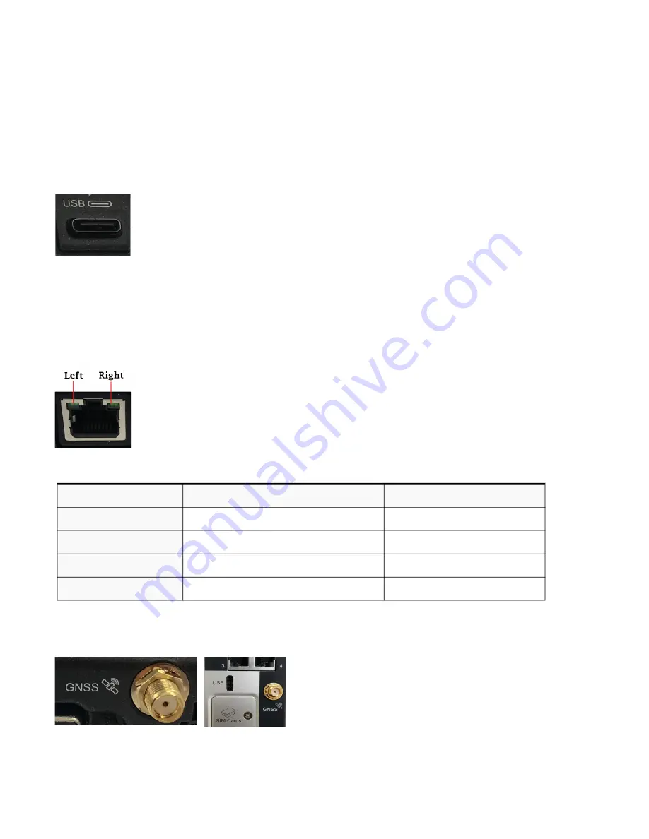
USB-C Port

The USB port is used as a console port providing direct access to CLI (Command Line 

Interface) as well as status, logging and troubleshooting information. In addition, this sport 

can increase the methods by which data can be sent and received from a connected 

computer. The USB port can be set as a Ethernet over USB port or as a console port. 

See 

Connecting to the USB-C port in Console Mode

 and 

Connecting to the USB-C port as 

an Ethernet over USB Port

.

Ethernet LAN Ports

Once the ports have been connected and the link is established, the speed LED will turn 

on. The LED will indicate whether you have a 10, 100 or 1000 Mbps link on the Ethernet 

port.

Ethernet Link Status

GNSS Connector

GPS+GAILEO

Passive Antenna – SMA(M) straight connector See Technical Specifications for 

electrical details.

Link/Speed Indicator

Description

Left LED Green

Link + Flashing with activity

1000 Mbps

Both LEDs

Link + Flashing with activity

100 Mbps

Right LED Green 

Link + Flashing with activity

10 Mbps

Off

Off

No LAN connected

Summary of Contents for C4G-M-4P6M

Page 1: ...EtherWAN C4G M 4P6M Router HardwareGuide ...

Page 2: ...n be found in the Cellular LTE Router Quick Start Guide that came with your product Key Features Supports bridging switching and routing LTE coverage spanning 30 frequency bands for global coverage Fully automatic network switching supporting dual network SIMs Routing with Primary Backup route LTE and VPN Fail over Provides network connectivity via LTE Ethernet USB C Active GPS for tracking equipm...

Page 3: ...nual is subject to change without notice and does not represent a commit ment on the part of EtherWAN for any and all direct indirect special general incidental consequen tial punitive or exemplary damages including but not limited to loss of profits or revenue or anticipated profits or revenue arising out of the use or inability to use any EtherWAN C4G M 4P6M series router even if EtherWAN has be...

Page 4: ...hnique de EtherWAN à l adresse https www EtherWAN com Warning If the ambient temperature is to exceed 50 C 122 F the unit should be installed in a restricted access location where access can only be gained by service personnel or users who have been instructed about the reasons for the restrictions applied to the location and about any precautions that shall be taken and access is through the use ...

Page 5: ...division 2 groupes A B C D Warning WARNING EXPLOSION HAZARD Do not connect or disconnect equipment unless power has been removed or the area is known to be non hazardous Avertissement DANGER D EXPLOSION ET D AVERTISSEMENT Ne pas connecter ou deconnecter l équipement tant que l alimentation n est pas débranchée ou que la zone n est pas dangereuse Warning WARNING EXPLOSION HAZARD Substitution of any...

Page 6: ...main L appareil devrait être monté de façon à ce que les antennes soient à au moins 20 cm 8 po de toute personne Warning Explosion hazard Do not connect or disconnect while the circuit is live or unless the area is free of ignitable concentrations Avertissement Risque d explosion Ne pas connecter ou deconnecter le circuit est sous tension ou à moins que la zone ne présente aucune concentration inf...

Page 7: ...ble protection against harmful interference when the equipment is operated in a commercial environment This equipment generates uses and can radiate radio frequency energy and if not installed and used in accordance with this hardware guide may cause harmful interference to radio communications Modifications to this product not authorized by EtherWAN could void the FCC approval and negate your aut...

Page 8: ...VII EtherWAN Series Router Hardware Installation Guide Preface Publishing History Date Revision Update Details April 2020 A 04 13 2020 Initial release ...

Page 9: ...necting the Antenna s 7 Connecting to the Ethernet Port 8 Connecting to the USB C port in Console Mode 8 Connecting to the USB C port as an Ethernet over USB Port 8 Connecting the Power 9 Operation 10 Reset Factory Default Safe Mode 10 Fast Setup 11 Managing the Router 12 Overheat Standby 13 I O Configurations 14 Pulse Counter Digital Input 14 Relay 14 Appendix A Technical Specifications 15 Append...

Page 10: ... support Application uses Remotely monitoring and controlling equipment on pipelines meters pumps and valves in any energy utility or industrial application Tracking the location of heavy equipment and assets in the field Providing reliable Internet access to a mobile workforce What s Included The following components are included with your product The router 2 LTE antennas depending on model Quic...

Page 11: ...P2 in order for the LEDs to light Off Router powered off Router powered off Green Solid Normal operating mode N A Power must be applied Green Blip N A Normal operating mode Green Flashing Booted No configuration N A Amber Blip Standby mode Standby mode Blips every 5 seconds Amber Flashing Router booting Router booting Red Blip Overheat standby Overheat standby Red Solid Hardware error Hardware err...

Page 12: ... N A Same as above Blip Not connected Not connected Same as above GNSS Normal Mode Power Saving Mode Special Notes Off Disabled Disabled Green Solid Location Fix Location Fix Turns off after 5 seconds Green Blip Initializing off Amber Flashing No Fix N A Amber Blip N A No Fix VPN Normal Mode Power Saving Mode Special Notes Off No VPN No VPN Green Solid VPN connected VPN connected Turns off after 5...

Page 13: ...g the antennas see Connecting the Antenna s For more information on recommended LTE Antenna specifications see Antenna s Internet Normal Mode Power Saving Mode Special Notes Off Disabled Disabled Green Solid Internet WAN connection Internet WAN connection Turns off after 5 seconds Green Blip Not connected N A Amber Solid Backup mode N A Red Solid Connection failed N A Red Blip N A Connection faile...

Page 14: ...C port in Console Mode and Connecting to the USB C port as an Ethernet over USB Port Ethernet LAN Ports Once the ports have been connected and the link is established the speed LED will turn on The LED will indicate whether you have a 10 100 or 1000 Mbps link on the Ethernet port Ethernet Link Status GNSS Connector GPS GLONAS GAILEO Passive Antenna SMA M straight connector See Technical Specificat...

Page 15: ...erWAN Series Router Hardware Installation Guide Hardware Terminal Block Power Connector The power plug has two power connections one relay connection and one digital input connection See Connecting the Power ...

Page 16: ...SB C port in Con sole Mode Inserting the SIM card TheC4G R 4P6M comes with two SIM sockets for mini SIM 2FF cards Ensure the power is disconnected before you insert the SIM card s 1 Using your Phillips screwdriver removed the two screws from the panel covering the SIM slots Gently pry the cover loose from the opening 2 Align the SIM card so that the SIM card will slide into the top slot slot 1 Eac...

Page 17: ...5 Start a terminal emulation program such as Putty or SecureCRT on the com port where you have connect the cable to the PC 6 Press the Enter key on the keyboard and the prompt will display See the EtherWAN Series Router CLI Reference Guide for more information on using CLI commands Connecting to the USB C port as an Ethernet over USB Port In this mode the USB C port behaves as if a PC is connected...

Page 18: ...ckup and powers the Router Wiring with suitable temperature ratings must be used Refer to specification section for details Use copper wire only if the terminal is only for connection to copper wire 1 Ensure the power source is off prior to connection 2 Strip both 18 22AWG wires 7 mm 2 76 inch 3 Loosen the terminal block screws and connect positive negative wires into the termi nals 4 Tighten term...

Page 19: ...Description LEDs System Status Restart Press and Release the Reset button when the router is running Power LED will begin to blink amber Reboots All configuration and files will remain the same Factory default Press Reset and Hold for 10 seconds when the router is running All LEDs flash Amber release Reset button then Power LED flashes Amber Reboots and resets the configuration to the EtherWAN fac...

Page 20: ... be asked to enter some basic operating parameters including setting up the initial user ID and password for the router To connect via the console port follow the instructions provided in Connecting to the USB C port in Console Mode If you wish to connect using a Web browser connect your PC Ethernet cable to an Ethernet port on the router Ensure that the PC is set up to use DHCP as the method for ...

Page 21: ... IP address on the before connecting with the WebManager CLI A text based Command Line Interface based on industry standard syntax and structure The CLI can be accessed from the console port Once a valid IP address is configured on the router Telnet SSH or the Web interface can also be used to access the router for administration purposes See the CLI Router Reference Guide for more information SNM...

Page 22: ... C 203 F setting for 5 minutes then your router will enter into Standby mode and remain in standby until the temperature returns to 5 C 9 F is below the primary high threshold value for 5 minutes The high threshold can be configured within Alarm Manager Primary High Threshold menu Note that any value below 60 C 140 F set for this threshold will be ignored and the value of 60 C 140 F will be used f...

Page 23: ...een 25 75 or a digital input to detect the state of a switch or to monitor an external device such as a motion detector a remote solar panel or a remote camera Digital input can also be used with the Standby Timer Relay Pins 5 and 6 of the power connector can be connected to an external circuit which will be controlled by the internal relay When the relay is engaged the external circuit will be co...

Page 24: ...Port 4 Ethernet 10 100 1000 Auto neg Isolation 1 5 kV IEEE 802 3 for 10Base T IEEE 802 3u for 100Base TX and 100Base FX IEEE 802 3ab for 1000Base T IEEE 802 3x for Flow Control USB 1 Type USB 3 0 Type C Can be used as a console or additional Ethernet port SIM 2 15 25mm 2FF Environmental Specifications Operating Temperature Ranges 40 C to 70 C 40 F to 158 F Storage Temperature 40 C to 85 C 40 F to ...

Page 25: ...CS EN 61000 4 8 PFMF EN 61000 4 11 EN 61000 4 16 EN 61000 6 4 2007 A1 2011 ISO 7637 2 2004 Hazloc ATEX Class 1 Zone 2 ANSI ISA 12 12 01 Class 1 Division2 Group A B C D Railway EN 50155 2017 Clause 4 3 6 EN 50121 1 2017 50121 3 2 2016 50121 4 2016 IEC 60571 2012 for Clause 12 2 8 and 12 2 9 IEC 62236 1 2018 62236 3 2 2008 62236 4 2018 GSM UMTS certifications PTCRB RED Environment Testing Shock and ...

Page 26: ...PS 1575 42 MHz Galilo 1575 42 MHz BeiDou 1561 098 MHz GLONASS 1602 MHz Bandwidth 45 MHz Impedance 50 Ohm VSWR 2 0 Typical Gain RHCP Polarization 4 dBic typical Axial Ratio at elevation 5 dB typical Cellular Cellular Telecom Regulatory Approvals FCC ICES RED PTCRB CTIA CE Carrier Certifications AT T Verizon Technical Specifications ...

Page 27: ...nology LTE Band 1 Band 2 Band 3 Band 4 Band 5 Band 7 Band 8 Band 12 Band 13 Band 20 Band 25 Band 26 Band 29 Band 30 Band 41 HSPA UMTS Band 1 Band 2 Band 3 Band 4 Band 5 Band 8 2100 1900 1800 1700 850 2600 900 700 700 800 1900 Block C 850 700 2300 2500 2100 1900 1800 1700 850 900 Technical Specifications ...

Page 28: ...29 Band 30 Band 32 Band 41 Band 42 Band 43 Band 46 Band 48 Band 66 HSPA UMTS Band 1 Band 2 Band 4 Band 5 Band 6 Band 8 Band 9 Band 19 2100 1900 1800 1700 850 2600 900 1800 700 700 850 850 800 850 700 700 2300 1500 2500 2300 3700 5200 3500 1700 2100 1900 1700 850 800 900 1700 850 Cellular EN 301 908 1 EN 301 908 2 EN 301 908 13 EN 62311 2019 IEC 62311 Ed 1 0 b 2007 EN 301 489 1 EN 301 489 17 EN 301...

Page 29: ...ity 224 mph for cellular connectivity Parameter Requirements Comments Antenna System LTE 4G External multi band 2x2 MIMO SMA connector antenna system if Ant2 includes GNSS then it must also satisfy these requirements Operating Bands Frequency range 704 902 928 960 MHz 1427 9 1575 42 MHz 1710 2170 MHz 2400 2480 2690 MHz Impedance 50 OHM Gain 2 3 dBi VSWR of Ant 1 and Ant 2 3 0 On all bands includin...

Page 30: ...21 EtherWAN Series Router Hardware Installation Guide Appendix B Label sample ...

Page 31: ...towards the rail This will snap the bottom hooks of the DIN rail clip onto the bottom of the DIN rail Removing the router from the DIN Rail 1 The DIN rail attachment clip has a slot at the bottom of the latch that is visible beneath the router when it is mounted 2 Insert a flat blade screwdriver into the slot and twist the base to release the clip Alternatively a downward force on the clip will re...

Page 32: ...23 EtherWAN Series Router Hardware Installation Guide Appendix D Mechanical ...

Page 33: ...and Troubleshooting Maintaining Easy access to the cables Cables are not bent constricted close to high amperages or exposed to extreme temperatures Front panel LEDs are easily visible Do not use solvents or cleaning agents on this router if case gets dirty wipe with a dry cloth ...

Reviews: