background image

Content

1.3 Precautions

Before you start to operate the device, read the whole attached user`s guide carefully.

Keep the user`s guide and refer to it in case you operate the device in future.

Observe all the rules and warnings included in the user`s guide.

Make sure the device is not damaged in any way. In case of doubt, do not operate the device and 

contact the supplier.

In case of doubt concerning a safe operation of device, contact the supplier.

Special attention should be paid to warning signs, housing or packaging of device.

Operate the device according to its intended use.

The device is not a toy,children should be prohibited from playing with it.

On no account can children play with any part of the packaging of this device.

Children should be prevented from accessing  small parts, for example, clamping screws, pins. 

These elements can be found on the equipment of device supplied and in case of swallowing they 

can lead to the choking of child.

No mechanical or electrical moddifications can be made in the device. Such modifications can 

cause the wrong operation of device,  incompatible with standards or they can influence the 

operation of device in a negative way.

No objects should be put into the device through gaps (for example ventilation gaps). This can 

cause short circuit, electrical shock, fire or damage to the device.

Make sure that no water, moisture, dust and dirt gets into the device. This can cause short circuit, 

electrical shock, fire or damage the device.

Make sure  the device is ventilated properly, do not cover  ventilation holes and provide a free 

flow of air around it.

The device should be installed inside the rooms.

Make sure that the device is not exposed to impacts and vibrations.

Connecting the device, make sure that electric parameters of power supply network are within 

the operation range of device.

Any connections must be compatible with the installation electrical wiring diagram and with 

national, or local regulations relating to electrical connections.

There is no part in this device that can be replaced by the user himself. All service operations 

except cleaning and setting up the function, should be carried out by the authorized service staff.

Before starting any maintenance operations, you must absolutely disconnect the device from 

power supply. 

No benzine, solvents or other chemical agents, which can damage the housing of device, can be 

used for cleaning the device. A soft cloth is recommended for this purpose.

estyma electronics

www.estyma.pl

page 5

PL20130612

Summary of Contents for CTP-02R

Page 1: ...WIRELESS SENSOR OF ROOM TEMPERATURE CTP 02R ...

Page 2: ...page 2 PL20130612 ...

Page 3: ...GNEO Slim 9 2 3 3 IGNEO Compact 10 2 3 3 IGNEO Compact 10 2 3 4 Settings in the controller of boiler 11 2 3 4 Settings in the controller of boiler 11 3 Utilization 11 3 1 Signal LEDs 11 3 2 Adjustment of temperature 11 4 Non standard configuration 12 4 1 Switches 12 4 1 1 Addressing 12 4 1 1 Addressing 12 4 1 2 Change of transmission mode 13 4 1 2 Change of transmission mode 13 4 1 3 Selection of ...

Page 4: ...ion a parallel operation of up to 8 transmitter receiver sets in the same residential building is possible The transmitter is powered by 2 AAA batteries The device operates correctly in the range from 0 C to 50 o C The controller operates only with the most modern controllers of Estyma company starting from Platinum Bio series It is operated not only by the main controller but also by CAN I O expa...

Page 5: ...vice in a negative way No objects should be put into the device through gaps for example ventilation gaps This can cause short circuit electrical shock fire or damage to the device Make sure that no water moisture dust and dirt gets into the device This can cause short circuit electrical shock fire or damage the device Make sure the device is ventilated properly do not cover ventilation holes and ...

Page 6: ...t have technical experience Connections made with the copper cable should be adapted to the operation at a temperature of up to 75ºC All the connections must be compatible with the installation electrical wiring diagram and national or local regulations about electrical connections 2 2 Location The device is intended for the installation only in enclosed spaces After choosing the place of installa...

Page 7: ... heat sources for example electronic equipment fireplace heater or direct insolation It is recommended that the controller be mounted at a height not less than 1 5 m over the floor 4 The receiver should be mounted near the controller 2 3 Connection to the controller In the figure below you will find a general operation diagram of CTP 02R set with controllers of IGNEO line estyma electronics www es...

Page 8: ... as a sensor of room temperature step by step instruction is presented in point 2 3 4 on page 11 5 End of installation You can operate the controller SIGNAL LEDs When installed correctly the red LED of transmitter should flash briefly every 1 5 minute sends information The green LED of receiver should light up after it has received the information from the transmitter If the set does not operate c...

Page 9: ... heating function and indicate CTP2 as a sensor of room temperature step by step instruction is presented in point 2 3 4 on page 11 6 End of installation You can operate the controller now SIGNAL LEDs When installed correctly the red LED of transmitter should flash briefly every 1 5 minute sends information The green LED of receiver should light up after it has received the information from the tr...

Page 10: ...of room temperature step by step instruction is presented in point 2 3 4 on page 11 5 End of installation You can operate the controller now SIGNAL LEDs When installed correctly the red LED of transmitter should flash briefly every 1 5 minute sends information The green LED of receiver should light up after it has received the information from the transmitter If the set does not operate correctly ...

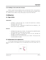
Page 11: ...been suspended so the battery should be removed and replaced RECEIVER LED flashes for 20 seconds every 1 5 minute the receiver gets the adjusted temperature from the transmitter in the normal mode every 1 5 minute LED flashes every second the receiver gets data all the time presumably the transmitter is in continuous transmission mode LED flashes twice for a short and long time every 5 seconds the...

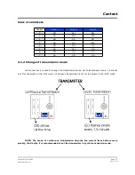
Page 12: ...Wall Platinum bio and IGNEO Compact Four switches placed inside the transmitter and receiver which are designated with number from 1 to 4 change standard settings for example to increase the number of CTP 02R sets or to change transmission or indications of controller 4 1 1 Addressing Addresses are determiend by the combination of the settings of three first switches in the transmitter and receive...

Page 13: ...number 4 is used to change the transmission mode Cyclic transmission every 1 5 minute is set for the switch in the ON mode Continuous transmission is set for the switch in the OFF mode NOTE The mode of continuous transmission absorbs the current from battery more quickly that is why it is recommended to set the transmitter in cyclic transmission mode estyma electronics www estyma pl page 13 PL2013...

Page 14: ...f receiver so that it shows the temperature sent by the transmitter In this case the switch in the transmitter number 4 should be in the OFF mode and then you should remove and replace the battery At that moment the transmitter will send the temperature of 23 ºC in the continuous transmission mode and the receiver is calibrated up to this temperature The second method calibration is made in relati...

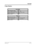
Page 15: ... length x height x width 71mm x 25mm x 71mm Spacing of mounting holes 60mm Weight of controller 52g Receiver Ambient temperature allowed 0 60 C Dimensions length x height x width 40mm x 30 3mm x 64mm Spacing of mounting holes 50 8 mm x 26 8 mm Weight of controller 38g estyma electronics www estyma pl page 15 PL20130612 ...

Page 16: ...Manufacturer Estyma electronics al Lipowa 4 11 500 Giżycko POLAND tel 48 87 429 86 75 fax 48 87 429 86 75 biuro estyma pl www estyma pl page 16 PL20130612 ...

Reviews: