MC404-Z
Document Version: 1.05
© 2021 All rights reserved.
25
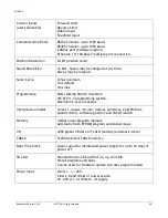
Feature
Requirements
Notes
0V wire (current return) 1. Always connect ALL 0V current return wires
2. Do not use the screen for 0V current return
3. It is highly recommended to avoid connecting
0V across internal isolation barriers.
If a single 24V supply is used for the main power
and IO power then these two isolated 0V will
have to be connected but this should only be
done if the 24V supply is free from switching
noise
4. Do not join together 0V from high power and /
or noisy sources with the 0V from signal ports
(incl. CAN bus DC input)
5. Do not use any controller 0V connection as a
current return for peripheral devices
MC404-Z stepper 0V, encoder
0V and Auxiliary connector 0V
are all common together.
24V supply 0V is isolated.
24V IO supply is isolated.
All 24V DC ports
1. It is highly recommended to use surge filters
on all DC supply and 0V return. If more than one
device is connected to the same PSU then this is
a requirement. See
Cable routing
1. Maintain 150mm separation of parallel Class I
and Class II cable (IEC 61000-5-2:1997)
2. Unless otherwise specified, all cables must be
<30m in length
Proximity to source of
disturbance
1. Place controllers and expansion modules as far
from mains cables, mains filters, contactors,
circuit breakers, drives, transducers or other
high power sources of EM disturbance as
physically possible within the enclosure design.
Enclosure / Safety
Cabinet design
1. Trio’s products should always be installed
within a locked cabinet with access limited to
authorised personnel only.
Differential Stepper /
Encoder Signals
1. Screened, twisted pair cable.
2. Connect screen to metal chassis at both ends
(See
3. 0V reference connected at both ends.
CAN bus
1. Screened, twisted pair cable with
characteristic impedance of 120 Ohm. (±10 Ohm)
2. Connect screen to Chassis at every node.
Connect screen to Aux
connector shell at MC404-Z.
0V on Aux connector, pins 4, 8
and 12 are common 0V.
Digital I/O
1. It is highly recommended to use a separate
PSU and 0V return. (The I/O is internally isolated
from the main 24V supply input.)
ADC / DAC
1. Use DAC 0V reference pin not common 0V
0V on Aux connector.
RS232 / RS422 / RS485
1. Screened cable.
Connect screen to Aux


