


MC404-Z
Document Version: 1.05
© 2021 All rights reserved.
24
Electromagnetic Compatibility
Trio Motion Technology products are certified to comply with the requirements of Annex I to
the Directive 2014/30/EU on Electromagnetic disturbance and Electromagnetic immunity. To
achieve this compliance, certain requirements or best engineering practices must be
implemented by the corresponding system designer.
Intended conditions of use
Trio Motion Technology products are designed for operation in Industrial environments with
high noise levels that may induce currents or electrical potentials that are damaging to
microelectronics. Our products are nevertheless designed and tested to withstand the level
of electromagnetic disturbance common to these environments, on the provision that the
appropriate EMC guidelines have been employed by a qualified competent system integrator.
The Trio Motion Technology product range is designed to be integrated, by the customer, as
a control system for industrial machines and auxiliary equipment.
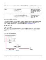
EMC Considerations
Electromagnetic Interference problems can usually be avoided by careful wiring and
following a few basic rules.
•
Mount noise generators such as contactors, solenoid coils and relays as far away as
possible from the Motion Coordinator.
•
Where possible use solid-state contactors and relays.
•
Fit suppressors across coils and contacts.
•
Place high voltage cables in separate trunking to low voltage and signal cables.
•
Ensure all the modules have a secure earth connection.
•
Where screened cables are used, terminate the screen with a
rat
her than a “pig
-
tail”. Connect both ends of the screen to earth. The screening
should be continuous, even where the cable passes through a cabinet wall or
connector.
These are just general guidelines and for more specific advice, see the installation
requirements later in this chapter.
The consideration of EMC implications is more important than ever since the introduction of
the EC EMC directive which makes it a legal requirement for the supplier of a product to the
end customer to ensure that it does not cause interference with other equipment and that it
is not itself susceptible to interference from other equipment.
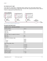
Product specific requirements
Trio Motion’s extensive product and application knowledge combined with product testing
reflect that the best immunity is achieved by placing some constraint on the system into
which the product is being integrated. The information is presented in this section for the
commissioning engineer.