background image


EP1000 PLC Quick User Manual 


16 

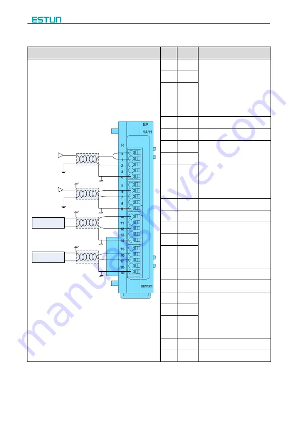
2.3.5 Wiring of Analog Module 

Diagram 

Pin 

Sign 

Description 

-20mA~20mA

Shield

-10V~10V

Shield

Shield

instrumentation

0~20mA

Shield

-10V~10V

instrumentation


R0 

Short 

R0

 and 

0+

, then 

combine with 

0-

: Channel 0 is 

used for current sampling; 

Combine 

0+

 with 

0-

: Channel 

0 is used for voltage sampling. 


0+ 

0- 

NC 

Reserved 

FG 

Ground Terminal 

R1 

Short 

R1

 and 

1+

, then 

combine with 

1-

: Channel 0 is 

used for current sampling;   

Combine 

1+

 with 

1-

: Channel 

1 is used for voltage sampling. 


1+ 

1- 

NC 

Reserved 

FG 

Ground Terminal


10 

I0 

Combine 

I0

 with 

M0

: Channel 

0 is used for current inputting;   

Combine 

V0

 with 

M0

: Channel 

0 is used for Voltage inputting. 


11 

V0 

12 

M0 

13 

NC 

Reserved


14 

FG 

Ground Terminal


15 

I1 

Combine 

I1

 with 

M1

: Channel 

1 is used for current inputting;   

Combine 

V1

 with 

M1

: Channel 

0 is used for Voltage inputting. 


16 

V1 

17 

M1 

18 

NC 

Reserved


19 

FG 

Ground Terminal


Summary of Contents for EP1000 PLC

Page 1: ...EP1000 PLC Quick User Manual Version V1 00...

Page 2: ...Version History No Date Version Description 1 2015 03 20 V1 00 Initial release...

Page 3: ...8 2 3 3 Wiring of Input Module 9 2 3 4 Wiring of Output Module 11 2 3 5 Wiring of Analog Module 16 2 3 6 Wiring of Power Supply Module 17 Chapter 3 Basic Operation 18 3 1 Connect to PC 18 3 2 Install...

Page 4: ...ication which make the PLC can be monitored the input status and changed the output status for the controlling Modular design and a powerful instruction set make the EP1000 a perfect solution for cont...

Page 5: ...EP1000 PLC Quick User Manual 2 INPUT EP1121 INPUT EP1161 RELAY EP1213 MOS EP1231 OUTPUT EP1234 OUTPUT EP1252 OUTPUT EP1222 ANALOG EP1A11...

Page 6: ...to study and design a micro PLC program and you can carry out the following task Set up PLC CPU type Create a PLC program Set up communication Set up System Block Design the program by using LAD or ST...

Page 7: ...housing cabinet or electric control room should be limited to authorized personnel Failure to follow these installation requirements could result in death or serious injury to personnel and or damage...

Page 8: ...ications cable connections For additional flexibility in configuring the layout of the EP1000 system use the I O expansion cable 150mm 150mm 150mm 150mm Mounting surface Front of the enclosure 150mm F...

Page 9: ...to ON or else it must be OFF 3 Install the other modules in proper sequence Left Right Push back the locker 4 3 Push back the locker of the right module 4 Install the other modules in proper sequence...

Page 10: ...uld cause electric shock or faulty operation of equipment Since the type of the terminal block is the spring crimp please use the split conductor for the wiring which the width is under 1 5 mm and it...

Page 11: ...sted pair RS485 Connection 3 core Cable Shielding Connect to the Shell of DB 3 485A Twisted pair 8 485B 2 GND Ground wire of RS485 5 GND Ground wire of RS485 Others Null 1 Tx Rx Green and White Orange...

Page 12: ...24VDC 24VDC 0 1M Common port for the ports of I0 to I8 1 I0 The input signal ports 2 I1 3 I2 4 I3 5 I4 6 I5 7 I6 8 I7 9 I8 10 2M Common port for the prots of I9 to I17 11 I9 The input signal ports 12...

Page 13: ...Description COM COM 24VDC 24VDC 0 1M Common port for the ports of I0 to I3 1 I0 The input signal ports 2 I1 3 I2 4 I3 5 2M Common port for the ports of I4 to I7 6 I4 The input signal ports 7 I5 8 I6...

Page 14: ...ring of Output Module EP1222 Diagram Pin Sign Description COM COM 0 1L Common port for the ports of Q0 to Q3 1 Q0 The output signal ports 2 Q1 3 Q2 4 Q3 5 2L Common port for the ports of Q4 to Q7 6 Q4...

Page 15: ...M COM 0 1L Common port for the ports of Q0 to Q3 1 Q0 The output signal ports 2 Q1 3 Q2 4 Q3 5 2L Common port for the ports of Q4 to Q7 6 Q4 The output signal ports 7 Q5 8 Q6 9 Q7 10 3L Common port fo...

Page 16: ...13 EP1234 Diagram Pin Sign Description 24VDC 24VDC 0 0V 24V 1 1L 0V 2 Q0 The output signal ports 3 Q1 4 Q2 5 Q3 6 Q4 7 Q5 8 Q6 9 Q7 10 0V 24V 11 2L 0V 12 Q8 The output signal ports 13 Q9 14 Q10 15 Q11...

Page 17: ...14 EP1231 Diagram Pin Sign Description 24VDC 24VDC 0 0V 24V 1 1L 0V 2 Q0 The output signal ports 3 Q1 4 Q2 5 Q3 6 Q4 7 Q5 8 Q6 9 Q7 10 0V 24V 11 2L 0V 12 Q8 The output signal ports 13 Q9 14 Q10 15 Q11...

Page 18: ...Manual 15 EP1213 Diagram Pin Sign Description 24VDC 24VDC 0 1L 24V 1 Q0 The output signal port 2 Q0 0V 3 Q1 The output signal port 4 Q1 0V 5 2L 24V 6 Q2 The output signal port 7 Q2 0V 8 Q3 The output...

Page 19: ...FG Ground Terminal 5 R1 Short R1 and 1 then combine with 1 Channel 0 is used for current sampling Combine 1 with 1 Channel 1 is used for voltage sampling 6 1 7 1 8 NC Reserved 9 FG Ground Terminal 10...

Page 20: ...EP1000 PLC Quick User Manual 17 2 3 6 Wiring of Power Supply Module Diagram Pin Sign 24V 1 24V 2 0V 3 PE...

Page 21: ...ur PLCs you can also use a standard Ethernet cross twisted pair for connecting the Ethernet interface of the EP1800 module 3 2 Install and Use EPX Programmer 3 2 1 Installing EPX Programmer Computer r...

Page 22: ...erifying the communication parameters for EPX Programmer Click on the Communication icon in Operation Bar and use the Communication dialog box to connect with your PLC as shown in You need set the par...

Page 23: ...create a very simple self starting timer that resets itself For this example you use the Ladder LAD editor to enter the instructions for the program The following example shows the complete program in...

Page 24: ...o enter the timer number and to move the focus to the preset time PT parameter 6 Enter the following value for the preset time 100 7 Press the Return key to enter the value Step 3 Entering Network 2 T...

Page 25: ...Press the Return key to enter the address for the contact To enter the coil for turning on M0 0 1 Select the output coil from the bit logic instructions 2 Hold down the left mouse button and drag the...

Page 26: ...s by displaying the current values The status chart also allows you to force or change the values of the process variables You can create multiple status charts in order to view elements from differen...

Page 27: ...EP1000 PLC Quick User Manual 24 Figure 3 4 Force a value The EP1000 PLC only allows you to force any or all of the I O points I and Q bits...

Page 28: ...EP1000 PLC Quick User Manual 25 Appendix A Modules Dimension CPU EP1900 25 29 9 105 7 75 5 Unit millimeter COMM EP18x0 20 9 105 7 79 5 Unit millimeter...

Page 29: ...EP1000 PLC Quick User Manual 26 INPUT EP1161 20 9 105 7 84 5 27 8 Unit millimeter RELAY EP1252 20 9 105 7 84 5 27 8 Unit millimeter...

Page 30: ...EP1000 PLC Quick User Manual 27 MOS EP1213 20 9 84 6 27 8 105 7 Unit millimeter POWER EP1002 20 9 27 8 84 5 105 7 Unit millimeter...

Page 31: ......

Reviews: