background image

Maintenance

E-S 1000D Series Instruction Manual

5.1


1) Lubricate the rear pivot and front pivot of the bracket.

2) Lubricate the gate hinges about every 3 months and also 
check for levelness of gate. 

Rear Pivot

Front Pivot

Summary of Contents for E-S 1000D Series

Page 1: ...l of force Excercise caution at all times and stay clear of the system during operation USER DRIVEN MANUAL Any feedback changes or advice we are glad to hear it Please contact us at support estateswing com EstateSwing suniqueuserdrivenmanualsareconstantlyupdatedbyinstallersandhomeownerslikeyourself Weimprovebyhearingandapplyingyourfeedback Large Steel Control Box Included ...

Page 2: ...system The irreversible system ensures the gate is mechanical locked when the motor is not operating A lock still needs to be installed if security or high winds are a concern Removal of the gate slide pin will manually allow the gate to be opened E S 1000D Series Instruction Manual A vehicular gate opener or system intended for use in a home of one to four single family dwelling or a garage or pa...

Page 3: ...on of Operator Pull to Open 2 4 5 Push to Open Illustration 2 6 IMPORTANT Determining Setback Push to Open 2 7 Installation of Operator Push to Open 2 8 9 Section 3 Gate Operator Mounting Wiring Motors and Power Mounting Gate Operator s Finding Limits 3 1 2 Control Box Running Wires 3 3 Easy Wiring Under Driveway 3 4 Removing Terminal Strips for Wiring 3 5 Wiring the Operator Arms s Pull Push to O...

Page 4: ...Section 1 Review of Specifications Warnings and Tools E S 1000D Series Instruction Manual ...

Page 5: ......

Page 6: ...on class IP44 Gate leaf max length ft Up to 12 Gate leaf max weight lbs Up to 600 Operator Type Screw Drive Operator Weight 14 lbs Gate Weight Length Ratio 6 8 10 12 100lbs X X X X 200lbs X X X X 300lbs X X X X 400lbs X X X 500lbs X X 600lbs X The above chart represents the maximum weight and length combinations that this gate opener can handle The lengths and weights are either for a single gate ...

Page 7: ...2 of Wire C Connector Pins and Clips D Wire Harness E 2 Gate Mounting Brackets F 2 Post Mounting Bracket Kits Not Shown Transmitter Receiver Pack Additional Wire Mounting Hardware 2 3 8 x1 3 8 Hex bolts washer nut 2 5 16 x 1 3 8 Hex bolt washer nut 4 3 8 x 2 Carriage bolt washers nut 2 1 4 x 2 Hex bolt washers nut Not Included Battery ...

Page 8: ... move smoothly without any irregular friction during entire travel Make sure the hinges are in good condition Ball bearing hinges are necessary for gates weighing over 200 lbs or over 10 in length Make sure the gate is plumb and level The gate post must be secured in the ground with concrete This will prevent alteration of alignments and leveling during installation and during cycles Notes 1 When ...

Page 9: ...ay be needed to achieve the appropriate desired setback The metal support bracket will be bolted or welded to your post to give a larger amount of space to mount the provided mounting bracket A voltage meter and digital camera may be necessary to run diagnostic checks If your transformer is going to be plugged into an outdoor outlet you will need to weatherproof that outlet and transformer Electri...

Page 10: ...Section 2 Installation of Mounting Brackets E S 1000D Series Instruction Manual ...

Page 11: ......

Page 12: ...e Gate To Manually Change Position of Piston 2 The shaft can now be turned to open and close manually 3 Replace pin to exit manual operation 1 Remove the pin as seen to the right 2 Swing motor off of the gate bracket 3 Swing gate and opener out of the way of vehicle and then reclose gate and re attach arm ...

Page 13: ...Instruction Manual 2 2 This means the gate operator is mounted on the inside of the property and pulls your gate in towards the property If you are going to use push to open operation X out the next 3 pages and use the push to open section instructions ...

Page 14: ...clearance before permanently attaching them Variations to the ideal setback can be made so long as the total is less than the combined measurements for the desired opening arc and the motor body is more than 2 inches away from the gate in both the open and closed position setback variations significantly reduces the length and weight capacity of the operator A B Sum a 4 5 10 110 5 5 10 1 2 100 5 5...

Page 15: ...erang bracket for cutting See Fig 2 4 Cut off the excess length if any of the boomerang bracket using a sawzall or hacksaw 5 Using a measuring tape measure vertically to find the center of the horizontal mount on the gate then place a mark See Fig 3 6 Utilizing a level measure from the center of the horizontal mount of the gate to the post to the get bracket position Place a mark on the post at th...

Page 16: ...omerang bracket Double check the setback on the boomerang bracket 12 Drill the set hole through all 3 brackets using a 5 16 drill bit in an area behind the first hole Secure the hole with a 5 16 bolt and the provided nuts and lock washers See Fig 8 13 WITH THE GATE IN THE CLOSED POSITION measure 44 from the center of the hole on the boomerang bracket to the center of the hole on the gate bracket t...

Page 17: ...es Instruction Manual 2 6 This operation is commonly used if your driveway slopes up after the gate preventing it from swinging in This means the gate operator is mounted on the inside of the property and pushes your gate out away from the property ...

Page 18: ... Clamp brackets on and test arm movement clearance before permanently attaching them To determine the position of the gate mounting bracket above is for the post mounting bracket refer to step 13 in the section Installation of operator PTO A B Sum a 4 5 10 110 5 5 10 1 2 100 5 5 11 90 Variations to the ideal setback can be made so long as the total is less than the combined measurements for the de...

Page 19: ...erang bracket for cutting See Fig 2 4 Cut off the excess length if any of the boomerang bracket using a sawzall or hacksaw 5 Using a measuring tape measure vertically to find the center of the horizontal mount on the gate then place a mark See Fig 3 6 Utilizing a level measure from the center of the horizontal mount of the gate to the post to the get bracket position Place a mark on the post at th...

Page 20: ...boomerang bracket Double check the setback on the boomerang bracket 12 Drill the set hole through all 3 brackets using a 5 16 drill bit in an area behind the first hole Secure the hole with a 5 16 bolt and the provided nuts and lock washers See Fig 8 13 WITH THE GATE IN THE OPEN POSITION measure 44 from the center of the hole on the boomerang bracket to the center of the hole on the gate bracket t...

Page 21: ...Section 3 Gate Operator Mounting Wiring Motors Power E S 1000D Series Instruction Manual ...

Page 22: ......

Page 23: ...ith a connector pin 2 Utilize the C clip pliers in order to attach a C clip on the bottom side of the connector pin 3 Move the gate along with the operator to the open position Manually turn the piston until it fits the bracket that is mounted on the gate Post G a t e 4 Temporarily secure the front of the arm with a clevis pin You will be locating and setting the limits in the next page ...

Page 24: ...rary pin and manually turn the piston until it fits the gate in the desired closed position As you close the gate you can leave the washer on the side and it will move along with the magnet 6 Move the other limit switch on the bottom to line up with the washer Once you set the limits secure the front side of the gate operator with the clevis pin and the cotter pin Underneath the arm there are slid...

Page 25: ...ator The junction box can be mounted on a post or a fence line Allow at least 3 feet of clearance off the ground 4 Insert operator cable and extension cable into the holes in the bottom of the junction box and seal with caulk You may also use a watertight connector and connector nut to secure the cables Found at your local hardware store 6 Insert wires from extension cable and operator cable into ...

Page 26: ...home supply store Dig a trench perpendicular to the driveway approximately 6 to 8 inches deep and 6 long Hook up a typical garden hose assembled to the first length of pipe as shown Turn on water and push the pipe under the driveway matching the pitch of the driveway If you hit a rock use the hammer to force the pipe past the rock Attach additional pieces of pipe to the initial length by removing ...

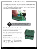
Page 27: ...e finished with your wiring connections Take the terminal block off of the control board to insert wires Hold with screw terminals facing upward Turn the screw counter clockwise to open the terminal and clockwise to close the terminal The terminals come closed Be sure not to mistake this for open and insert the wires below the terminal clamp This will lack the conductivity to complete the circuit ...

Page 28: ...s E S 1000D Series Instruction Manual 3 6 For a dual gate use the provided wire to connect the secondary motor to the control board It is important to choose the correct operation type Pull to Open Opening in towards property ...

Page 29: ... E S 1000D Series Instruction Manual 3 7 For a dual gate use the provided wire to connect the secondary motor to the control board It is important to choose the correct operation type Push to Open Opening out towards the street ...

Page 30: ...witch 1 OFF If the dip switch is set to on the gate will autoreclose after turning it on without any intentional activation on your part ON Auto Close on the gate will re close from the open position after a time set in the programming section OFF Auto Close off ON Dual gate opener 2 motors OFF Single gate opener 1 motor ON Gate lock terminals active OFF Gate lock terminals inactive 1 2 3 Dip Swit...

Page 31: ...ailable at autopart stores home stores and battery stores Allow a minimum of 4 of wire between the charge board and the transformer if using the plug in option Battery charging is done directly to the battery through a solar panel or charge controller See the samples below Solar Option Plug In Option Battery Solar Controller Solar Battery Control Board Control Board Battery Charge Board 4 Spade Co...

Page 32: ...Section 4 Start Up Operation E S 1000D Series Instruction Manual ...

Page 33: ......

Page 34: ... get P4 setting to 3 9 Press SET button 10 LED shows P5 Press Push 1 to get P5 setting to 2 11 Press SET button 12 LED shows P6 Press Push 1 to get P6 setting to 10 13 Press SET to finish You should hear 3 beeps this indicates parameter programming is finished This is our recommended procedure to run the gate for the first time Set Push 1 Push 2 Manually detach the end of the gate opener then turn...

Page 35: ...rt of or further than desired position adjust the limit switches After you have your limits in the correct position secure the position of the switches with the screws and run your gate through a few cycles On the display you will see a count while the arms are moving This is your run time Record your run time below ACTUAL RUN TIME _____________________________ Opening Limit Switch Closing Limit S...

Page 36: ...tor take to move from one limit to the other 3 LED shows P3 P3 is the force setting the lower the number the easier the gate will reverse directions when it meets resistance This number may have to be changed to a higher setting if your gate is obstructing unexpectedly The number should be set to the highest number during initial setup and reduced to the point of reliable operation that takes into...

Page 37: ...Section 5 Maintenance Troubleshooting Accessories E S 1000D Series Instruction Manual ...

Page 38: ......

Page 39: ...nce E S 1000D Series Instruction Manual 5 1 1 Lubricate the rear pivot and front pivot of the bracket 2 Lubricate the gate hinges about every 3 months and also check for levelness of gate Rear Pivot Front Pivot ...

Page 40: ...correct it will limit how far the gate will move per inch of stroke length If the gate will open but will not close Manually move the gate slightly off the open position by turning shaft and re attaching to gate then trigger the gate to go closed If the gate then moves closed the limits are most likely wired backwards Meaning open limit is wired to closed and closed wired to open If you are not us...

Page 41: ...e correctly in the terminal blocks The terminal blocks come with the terminal clamps closed however when the terminal clamps are closed there is a small space below them one could mistake as place to insert a wire If this is done then conductivity of the connection will never be reached General fixes for user to understand operation Unhook the gate opener arm and move it to the half way position C...

Page 42: ...uired to e mail digital photos to the technician This is done in your best interest to save unnecessary shipping expenses and time lost Many times we can come up with solutions to issues by seeing pictures that relay information that is impossible to relay through a phone conversation Below are examples of control board pictures and motor pictures that we will be looking for Pictures shown are act...

Page 43: ... contact will move the gate in the direction opposite what it was moving before stopped 4 When open and counting auto reclose pause time momentary contact will stop pause time 5 Stopped in open position from override of auto reclose from PUSH1 or Receiver momentary contact will reactivate pause time and close gate 6 When closing momentary contact will stop the gate and then it will auto reclose Op...

Page 44: ...contact will move the gate in the direction opposite what it was moving before stopped 4 When open and counting auto reclose pause time momentary contact will override reclose count and immediately close gate 5 When closing momentary contact will stop the gate and then it will auto reclose Operational Sequence for terminal with autoclose OFF Dip switch 1 in off position 1 In closed position moment...

Page 45: ... contact will have no effect 3 When stopped mid cycle from PUSH 1 or the Receiver momentary contact will open the gate 4 When open with auto reclose on momentary contact will re set pause time and will start counting again after release of momentary contact 5 When pause time countdown is stopped in open from a momentary contact of PUSH 1 or the Receiver momentary contact will have no effect 6 When...

Page 46: ...tion V 12VDC Max 50 milliamps for photocell power 12v Accessory power max 350 milliamps PUSH 1 Ground for Push 1 Accessory COM Positive voltage 12VDC for Push 1 2 accessory relay only not main power PUSH 2 Ground for Push 2 accessory PUSH 1 COM is for push buttons keypads receivers or any other dry and momentary contact PUSH 2 COM is for exit wand exit loops or other open only dry contact and mome...

Page 47: ...ock OP Opening cycle AU Auto reclose countdown CL Closing cycle PH Photocell is tripped or not jumped LU Low Voltage Lock Out Buzzer Obstructions If the gate s come in contact with an obstruction the gate s will reverse direction for 2 seconds and stop to allow the obstacle to be cleared from the gate path If the gate s obstructs 3 times in a row the gate s will go into a hard shutdown mode and a ...

Page 48: ...bbr N C Indicates that in order for the gate opener to be active this circuit must be closed When a device opens this circuit it stops the motion of the gate operator This circuit is the main circuit for safety devices i e photo eyes safety loops etc Common abbr COM This is the matching terminal for both Normally Open and Normally Closed circuits to be connected to Accessory wiring that begins in ...

Reviews: