background image

1. M

ETHOD

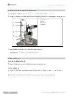
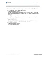
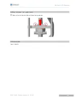
Cleaning the lens and reflecting mirror

If there is any dust on the lenses or reflecting mirror, wipe it off with soft cotton dipped in absolute
alcohol.

1. Prism
2. Objective

Do not touch the lens with finger or hard object. 

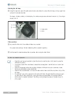
Cleaning the sliding pad, rails and shaft

Clean these parts with clean soft cloth regularly to ensure the stable movement of slit lamp.

1. Rail
2. Shaft
3. Slide plate

Cleaning and disinfecting the plastic parts

Clean the plastic parts such as chinrest bracket, forehead-rest belt with soft cloth dipped in soluble
detergent or water, and then disinfect these parts with medicinal alcohol.

Don't wipe these parts with any corrosive detergent in case any surface damage caused.

1

1

1

SL300L / SL400L - Slit lamp microscope > V2 - 03-2018

34

U

SER


MANUAL

> VI. C

LEANING

Summary of Contents for SL 300

Page 1: ...www essilor instruments com User manual...

Page 2: ...cations 12 6 Marks on device 12 7 Indicator lamp 13 8 Installation and working condition 13 9 Component list 13 10 Transport and storage 13 III NOMENCLATURE 15 IV ASSEMBLY 19 1 Main parts check list 2...

Page 3: ...1 Protection 38 2 How to replace the fuse 38 3 How to replace the chinrest paper 39 4 Consumables 39 VIII TROUBLESHOOTING GUIDE 41 IX APPENDIX 43 USER MANUAL CONTENTS...

Page 4: ...I INTRODUCTION...

Page 5: ...manual Labels and marks required by IEC 60601 1 standard is stuck on the instruments and described in this user manual Working principle A beam of light attached to the slit lamp projects to the pati...

Page 6: ...5 5 mm 25X 8 5 mm 16X 13 5 mm 10X 22 mm 6X 34 7 mm b Slit illumination TECHNICAL DATA VALUE Slit width Continuously variable from 0 to 14 mm at 14 mm slit becomes a circle Slit lenght Continuously var...

Page 7: ...ight TECHNICAL DATA VALUE Dimension 740 mm x 450 mm x 550 mm Gross weight 22 Kg Net weight 16 Kg h Environmental conditions PHASE TECHNICAL DATA VALUE Transport Temperature 40 C 55 C Atmospheric press...

Page 8: ...II SAFETY AND PRECAUTIONS...

Page 9: ...pay attention to all the ratings of the electrical connecting terminal 5 Turn OFF the main power first before replacing the main bulb flash lamp and fuse 6 When replacing the power cable please use th...

Page 10: ...alue F1AL250V Power At the front of power supply box switch the power ON and OFF Voltage selector Switch the input voltage from 110V to 220V The mark of light dimmer 3 EMC PRECAUTIONS Other medical in...

Page 11: ...A 7 Classification Detail in safety marks table 8 Working time No indication work continuously 9 Fuse Detail in safety marks table 10 Output Detail in safety marks table 11 Physiological reaction No i...

Page 12: ...tall the instrument according to this user manual Test and ensure the instrument operating well before putting to use 9 COMPONENT LIST The following electronic components are used in this instrument N...

Page 13: ...III NOMENCLATURE...

Page 14: ...b will be shortened 4 Base locking screw The base will be locked when fastening this screw 5 Illumination arm locking knob When locking the screw the illumination system and checking system were conne...

Page 15: ...g observed in a stationary state 12 Forehead belt Make patient s head in an appropriate position 13 Applanation tonometer adapter 14 Magnification select dial Dial it five or three different magnifica...

Page 16: ...IV ASSEMBLY...

Page 17: ...HECK LIST NAME QUANTITY IMAGE Chinrest part 1 Microscope part 1 Illumination part 1 Tabletop part 1 Rail cover 1 Power cable 1 Focusing test bar 1 Dust proof cover 1 Chinrest paper 1 Screw driver 1 Us...

Page 18: ...serted into the power box Spare fuse are provided in the box Remove A team screws 4 M6 x20mm under the tabletop Lift the tabletop to align its screw holes to the assembly holes of the instrument table...

Page 19: ...e way as below Take out the slit lamp part put it on the rails of the tabletop and ensure the gears well connected Move the base to confirm the wheels rolling steadily and then cover the rails with ra...

Page 20: ...w 4 Limit pin 5 Body 6 Insert Make sure the main power plug is not connected Take out the wire of brightness control knob on the base and connect it to the corresponding socket on the power box Insert...

Page 21: ...limit groove on the socket Please align the plug with the groove Wrong power selection may lead to damage of the instruments Open the fuse box and make sure there is a fuse assembled Specification of...

Page 22: ...ator lamp will be lighted when the instrument is power ON Insert the focus test bar to right position A light spot will be projected on the focus test bar Rotate the slit width knob to adjust the widt...

Page 23: ...ght dimmer knob and the brightness will go dim Turn OFF the main power and cover the instrument with the dust proof cover after testing 7 8 SL300L SL400L Slit lamp microscope V2 03 2018 26 USER MANUAL...

Page 24: ...V OPERATION PROCEDURES...

Page 25: ...the correct poison of slit lamp With the focal plane facing to the objective lens Remove the bar after testing 1 Test bar 2 Focus plane Brightness adjustment Switch ON the main power Rotate the light...

Page 26: ...te the diopter adjustment ring counter clockwise to the end Rotate the ring clockwise until the slit image is sharp Adjust the other eyepiece in the same way If necessary record the diopter value on e...

Page 27: ...fixation target at a proper position The fixation point is used to attract patient s attention 3 BASE OPERATION Horizontal rough adjustment Move the base back and forth to align microscope with patien...

Page 28: ...rom sliding Locking screw 4 OPERATION OF ILLUMINATION SYSTEM Changing the aperture and slit height Rotate the aperture and slit height dial to get four round light spots of different diameter sizes 14...

Page 29: ...to learn the structure and function of slit lamp for using the instrument properly In order to prevent the unnecessary observation misjudgment read the scales on each knob carefully Operator should a...

Page 30: ...VI CLEANING...

Page 31: ...with clean soft cloth regularly to ensure the stable movement of slit lamp 1 Rail 2 Shaft 3 Slide plate Cleaning and disinfecting the plastic parts Clean the plastic parts such as chinrest bracket fo...

Page 32: ...and thus affect the observed optical effect 2 Cleaning the slide pad rails and shaft Cycle suggested once per month Usually these parts won t get dirty in normal use We suggest cleaning these parts o...

Page 33: ...VII MAINTENANCE...

Page 34: ...on the power box Spare fuses are provided with this instrument For more fuses purchase from your local supplier Switch OFF the main power and remove the power cable from socket The fuse is inserted in...

Page 35: ...3 HOW TO REPLACE THE CHINREST PAPER Remove the two fixation bolts and place the new papers 4 CONSUMABLES Fuse F1AL250 1 USER MANUAL VII MAINTENANCE 39 SL300L SL400L Slit lamp microscope V2 03 2018...

Page 36: ...VIII TROUBLESHOOTING GUIDE...

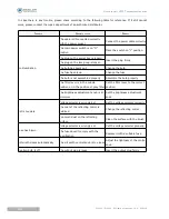
Page 37: ...middle position or in the position of gray filter Set the filter lever to the correct position The brightness adjustment knob is at minimum Set the brightness adjustment knob Slit is too dark Voltage...

Page 38: ...IX APPENDIX...

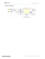
Page 39: ...Electrical circle drawing SL300L SL400L Slit lamp microscope V2 03 2018 44 USER MANUAL IX APPENDIX...

Page 40: ...Essilor Instruments USA 8600 W Catalpa Avenue Suite 703 Chicago IL 60656 Phone 855 393 4647 Email info essilorinstrumentsusa com www essilorinstrumentsusa com...

Reviews: