background image

SETTING UP A CAMERA DETECTOR 

WeR@Home™ WeR+ Installation Guide 

33 


7.1.


Choosing an Installation Location 

Choose an installation location that is: 


Indoors 


On a flat, clean, dry, and smooth surface 


Within 12 m (39.4 ft.) of the desired coverage area. 


Has detection area within 90° 


Do not 

choose an installation location that is: 


Outdoors 


Directly facing a window 


Near blowing curtains 


In an area of high humidity  


Near an air conditioner, heater, or ceiling fan 

Summary of Contents for WeR@Home WeR+

Page 1: ...WeR Home WeR Installation Guide June 2021...

Page 2: ...ing the Curtain Detector 21 5 4 Testing the Curtain Detector 25 Setting Up the S5 Door Window Sensor 26 6 1 Choosing an Installation Location 26 6 2 Preparing the Required Equipment 27 6 3 Installing...

Page 3: ...tary and Confidential 3 Hub ES8400CP 46 S5 47 Camera Detector ES800IPD 48 Siren ES800SRN 48 Keypad Tag Reader ES800TRKPD 49 Remote Control ES800KF 49 FCC and IC Safety Notice 50 Appendix B Installing...

Page 4: ...rtphone app enables you to monitor and control your home even while you are away from it The hub coordinates the functioning of peripheral devices that include sensors detectors and access control dev...

Page 5: ...INSTALLING THE WER HOME APP WeR Home WeR Installation Guide 5 Installing the WeR Home App To download and install the WeR app from the Apple App Store or the Google Play Store scan the QR code...

Page 6: ...s the following Choosing a location Connecting the hub 3 1 Choosing a Location Choose a hub location that is Central within the premises A flat surface Near a network connection or router Strong cellu...

Page 7: ...UP THE HUB WeR Home WeR Installation Guide 7 3 2 Connecting the Hub To set up the hub 1 Remove the back cover 2 If your kit included a SIM card insert it now 3 Insert the backup battery and close the...

Page 8: ...HE HUB 8 WeR Home WeR Installation Guide 4 Connect the power cable and plug it into a power source 5 Connect a network cable to the hub and connect the other end to a network port Wait for the LED to...

Page 9: ...ttom of the hub 7 On your smartphone tap The WeR app Welcome screen appears 8 If you do not have a user ID tap Sign up Follow the onscreen instructions 9 If you already have a user ID log in The Add a...

Page 10: ...the S5 Motion Detector The S5 motion detector is a wireless device that detects movement within a room The motion detector setup includes the following Choosing an installation location Preparing the...

Page 11: ...cation Choose an installation location that is Indoors On a flat clean dry and smooth surface Has detection area within 90 Do not choose an installation location that is Outdoors Directly facing a win...

Page 12: ...line batteries Flat head screwdriver If installing with screws Drill Philips head screwdriver Two 3 X 35 DIN 7982 C screws and wall anchors not provided 4 3 Installing the Motion Detector To install t...

Page 13: ...allation Guide 13 2 Remove the motion detector from the wall mount 3 If the motion detector was included in the kit continue with step 8 4 From the WeR app tap The menu appears 5 Tap Devices The Devic...

Page 14: ...ompartment Follow the onscreen instructions 8 Insert the batteries into the motion detector observing the correct polarity 9 To install with screws refer to Appendix B Installing with Screws on page 5...

Page 15: ...Ensure that the motion detector is right side up 12 To install in a corner or angled on a wall peel one side of a tape and affix it to the angled side 13 Peel the tape 14 To install flush against a w...

Page 16: ...tape 16 Press the motion detector into the corner or against the wall at a height of 2 2 m 7 2 ft 4 4 Testing the Motion Detector Test the motion detector within three minutes of installation To test...

Page 17: ...or The S5 curtain detector senses motion in front of a window or group of windows The coverage area is narrow like a curtain The curtain detector setup includes the following Choosing an installation...

Page 18: ...n Guide 5 1 Choosing an Installation Location Choose an installation location that is Indoors On a flat clean dry and smooth surface Do not choose an installation location that is Outdoors In an area...

Page 19: ...19 The curtain detector can be installed On the ceiling centered over the window NOTE Use screws for ceiling installation On a wall or the side of the window frame At a height of 1 5 m 4 9 ft Within...

Page 20: ...Installation Guide 5 2 Preparing the Required Equipment Prepare the following Two new 1 5V AAA alkaline batteries Flat head screwdriver If installing with screws Drill Philips head screwdriver Two 3 X...

Page 21: ...t head screwdriver into the slot indicated by the screwdriver icon The wall mount separates from the curtain detector 2 Remove the curtain detector from the wall mount 3 If the curtain detector was in...

Page 22: ...batteries into the curtain detector observing the correct polarity 9 To install on the ceiling a Drill out the hole guides as follows b Position the wall mount against the ceiling c Mark the position...

Page 23: ...l or window frame with screws refer to Appendix B Installing with Screws on page 52 11 To install on a wall or window frame with tape a Peel one side of a tape and affix it to the side of the wall mou...

Page 24: ...Home WeR Installation Guide c Press the wall mount against the wall or window frame d Ensure that the curtain detector is right side up e Place the curtain detector against the wall mount and press un...

Page 25: ...the Curtain Detector Test the curtain detector within 30 minutes of installation To test the curtain detector 1 Extend your hand through the coverage area Check that the LED lights red 2 After a few s...

Page 26: ...tector and magnet are positioned next to each other The door window sensor setup includes the following Choosing an installation location Preparing the required equipment Installing the door window se...

Page 27: ...stallation Guide 27 6 2 Preparing the Required Equipment Prepare the following Two new 1 5V AAA alkaline batteries Flat head screwdriver If installing with screws Drill Philips head screwdriver Two 3...

Page 28: ...lat head screwdriver into the slot indicated by the screwdriver icon The wall mount separates from the motion detector 2 Remove the door window sensor from the wall mount 3 If the door window sensor w...

Page 29: ...artment Follow the onscreen instructions 8 Insert the batteries into the door window sensor observing the correct polarity 9 To install with screws refer to Appendix B Installing with Screws on page 5...

Page 30: ...DOOR WINDOW SENSOR 30 WeR Home WeR Installation Guide 11 Peel one side of a tape and affix it to the back of the wall mount 12 Peel the tape 13 Press the door window sensor into place 14 Peel the tap...

Page 31: ...tor 16 Press the magnet into place 6 4 Testing the Door Window sensor To ensure proper operation test the door window sensor within 30 minutes of installation To test the door window sensor 1 Open the...

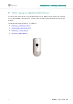
Page 32: ...frared PIR motion detector with a image capture camera You can use the WeR app to view both comfort images and security images captured when motion is detected The camera detector setup includes the f...

Page 33: ...on location that is Indoors On a flat clean dry and smooth surface Within 12 m 39 4 ft of the desired coverage area Has detection area within 90 Do not choose an installation location that is Outdoors...

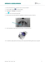
Page 34: ...ling with screws Drill Philips head screwdriver Two 3 X 35 DIN 7982 C screws and wall anchors not provided 7 3 Installing the Camera Detector To install the camera detector 1 Release the camera detect...

Page 35: ...ap The menu appears 6 Tap Devices The Devices screen appears 7 Tap The scanning window appears 8 Scan the QR code inside the battery compartment Follow the onscreen instructions 9 Insert the batteries...

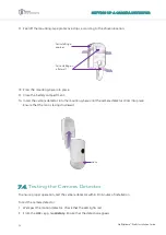
Page 36: ...r into the mounting base until the camera detector clicks into place Ensure that the lens is facing downward 7 4 Testing the Camera Detector To ensure proper operation test the camera detector within...

Page 37: ...n location Preparing the required equipment Installing the siren 8 1 Choosing an Installation Location Choose an installation location that is accessible but difficult for intruders to find that is In...

Page 38: ...siren 1 Release the siren wall mount by lifting the tab and sliding the base in the tab s direction 2 Press the tamper switch several times as in the figure below 3 If the siren was included in a kit...

Page 39: ...attery compartment Follow the onscreen instructions 8 Insert the batteries observing the correct polarity 9 To install with screws refer to Appendix B Installing with Screws on page 52 10 Replace the...

Page 40: ...d that also verifies user identity using RFID tags The keypad tag reader setup includes the following Choosing an installation location Preparing the required equipment Installing the keypad tag reade...

Page 41: ...river Three 3 X 35 DIN 7982 C screws and wall anchors not provided 9 3 Installing the Keypad Tag Reader To install the keypad 1 Release the keypad s wall mount by lifting the tab and sliding the base...

Page 42: ...PAD TAG READER 42 WeR Home WeR Installation Guide 7 Scan the QR code in the battery compartment 8 Press the tamper switch several times 9 Enter a name and configure outdoor and doorbell settings Tap O...

Page 43: ...Home WeR Installation Guide 43 10 Insert the batteries observing the correct polarity 11 Align the wall mount onto the keypad and slide the base into place 12 Peel off the mounting tape protective str...

Page 44: ...e control 1 Remove the battery compartment cover by inserting a coin into the slot and turning counterclockwise until the two dots align 2 Open the WeR app 3 Tap The main menu appears 4 Tap Devices Th...

Page 45: ...ACTIVATING A REMOTE CONTROL WeR Home WeR Installation Guide 45 8 Insert the battery into the battery compartment with the pole facing out and close the cover by turning it clockwise 9 Tap OK...

Page 46: ...etting and support for 700 1700 2100 1900 2500 2700 MHz bands Power 100 240 V AC to 5 V DC power adapter charger 3 7 V 1 4 Ah Li polymer rechargeable backup battery Maximum three hours battery life Di...

Page 47: ...elerometer mechanism Motion detection range Motion detector Up to 8 m 26 3 ft Curtain detector Up to 4 m 13 1 ft Power Batteries Two AAA 1 5 V alkaline batteries Battery life Three years Dimensions Si...

Page 48: ...onal up to 30 kg 66 lb pet immune lens Temperature compensation for the motion detector element Power Three AA size alkaline batteries One year battery life Dimensions Size H x W x D 123 x 58 x 60 mm...

Page 49: ...m Proprietary bi directional radio protocol Modulation and frequency DSSS 2 4 GHz RFID band ISO 14443a MiFare 106 kbps 13 56 MHz Data security 128 bit AES encryption Security Tamper alarm when detache...

Page 50: ...pareil doit accepter tout brouillage radio lectrique subi m me si le brouillage est susceptible d en compromettre le fonctionnement Changes or modifications to this equipment not expressly approved by...

Page 51: ...ment off and on the user is encouraged to try to correct the interference by one or more of the following measures Reorient or relocate the receiving antenna Increase the separation between the equipm...

Page 52: ...th screws S5 Motion detector S5 Curtain detector S5 Door window sensor Camera detector Siren Keypad S5 Motion Detector To install the motion detector with screws 1 To install in a corner or angled on...

Page 53: ...e screws through the holes in the wall mount 5 Drill holes where marked and insert the wall anchors 6 Align the wall mount with the wall anchors 7 Screw the screws through the wall mount into the wall...

Page 54: ...hole guides as follows 2 Position the wall mount against the wall or window frame at half the height of the window 3 Mark the position of the screws on the wall or window frame through the holes in th...

Page 55: ...guides as follows 2 Position the wall mount against the door door frame window or window frame 3 Mark the position of the screws through the holes in the wall mount 4 Drill holes where marked and inse...

Page 56: ...he mounting base has eight holes to allow for installation flexibility Varying combinations of holes allows you to install the camera or motion detector Flat on a wall On an angle facing to the right...

Page 57: ...wall a Remove the punch outs 1 and 2 using a flat screwdriver b Place and hold the base on the desired mounting location and mark the drilling spots c Drill the holes d Insert the wall anchors if nee...

Page 58: ...mount by lifting the tab and sliding the base in the tab s direction 2 Remove the punch outs using a flat screwdriver 3 Place and hold the base on the desired mounting location 4 Mark the drilling loc...

Page 59: ...Release the keypad wall mount by lifting the tab and sliding the base in the tab s direction 2 Place and hold the base on the desired mounting location 3 Mark the drilling locations according to the...

Page 60: ...the above disclaimers exclusions or limitations may not apply to you By using the information contained herein you agree that the laws of the State of Israel without regard to principles of conflict o...

Reviews: