Overview
1. Overview
1.1 Description of the Module
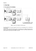
Figure 1:
Block circuit diagram of CAN-PCI/200
The CAN-PCI/200 is a PC board designed for the PCI bus. It is available with one or optional two
CAN interfaces.
The ISO 11898 compliant CAN interfaces allow a data transfer rate of 1 Mbit/s. Among many other
features, the bit rate can be set by software. The CAN interface is electrically isolated from the
other potentials by optocouplers and DC/DC-converters.
Page 6 of 23
Hardware Manual • Doc. No.: C.2021.21 / Rev. 1.1
CAN-PCI/200
+5 V=
+5 V=
+5 V=
+5 V=
C
A
N
B
U
S
CAN
CAN
IRQ A
Physical
CAN
Layer
C
A
N
B
U
S
electrical isolation
DC/DC
Converter
DSUB9
CiA pinning
CAN Controller
SJA1000
PCI Bridge
PLX PCI9052
electrical isolation
DC/DC
Converter
PCI Card Edge Connector
CAN Controller
SJA1000
Physical
CAN
Layer
DSUB9
CiA pinning
2nd CAN Interface
only at
CAN-PCI/200-2


