background image


Isotherm 

User 
Manual 

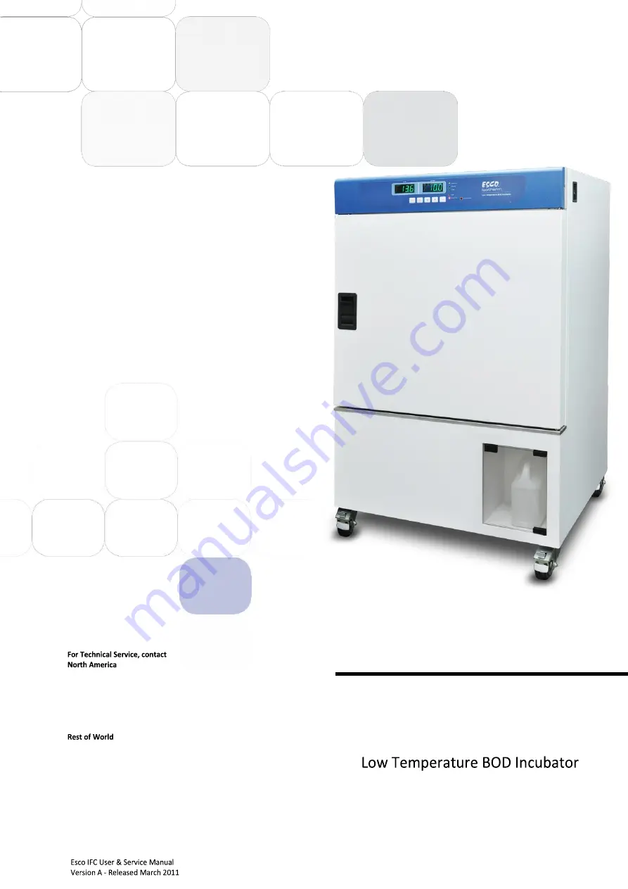
Thank you for purchasing this Esco Low Temperature BOD 
Incubator. Please read this manual thoroughly to familiarize 
yourself with the many unique features and exciting 
innovations we have built into your new equipment. Esco 
provides many other resources at our website, 
www.escoglobal.com, to complement this manual and help you 
enjoy many years of productive and safe use of your Esco 
products. 

Esco Technologies, Inc. 
2940 Turnpike Drive, Units 15-16  •  Hatboro, PA 19040, USA 
Toll-Free USA and Canada 888-375-ESCO  
Tel 215-441-9661  •  Fax 215-441-9660            
us.escoglobal.com  •  [email protected] 


Esco Micro Pte. Ltd.  
21 Changi South Street 1  •  Singapore 486 777 
Tel +65 6542 0833  •  Fax +65 6542 6920 
www.escoglobal.com  •  [email protected] 


Summary of Contents for Isotherm IFC-110-8

Page 1: ...esources at our website www escoglobal com to complement this manual and help you enjoy many years of productive and safe use of your Esco products Esco Technologies Inc 2940 Turnpike Drive Units 15 16 Hatboro PA 19040 USA Toll Free USA and Canada 888 375 ESCO Tel 215 441 9661 Fax 215 441 9660 us escoglobal com usa escoglobal com Esco Micro Pte Ltd 21 Changi South Street 1 Singapore 486 777 Tel 65...

Page 2: ... of such change Isotherm are registered trademarks of Esco Material in this manual is provided for informational purposes only The contents and the product described in this manual including any appendix addendum attachment or inclusion are subject to change without notice Esco makes no representations or warranties as to the accuracy of the information contained in this manual In no event shall E...

Page 3: ...ments 6 2 2 Installation 6 2 2 1 Caster Wheel 6 2 2 2 Water Container 6 2 3 Disclaimer 7 Chapter 3 Control System and Operation 7 3 1 Control System 7 3 1 1 Function Keys 7 3 1 2 LED Indicators 7 3 2 Unit Operation 7 3 2 1 Switching ON OFF 7 3 2 2 Opening Closing the Outer Door 8 3 2 3 Setting Temperature 8 3 2 4 Protection Devices 8 3 2 5 Auto Defrosting 8 3 2 6 Placement of Loads 9 3 3 Menu Opti...

Page 4: ... panel 14 4 2 4 Work Zone Decontamination 14 4 3 Physical Inspection 14 4 3 1 Re Adjustment of Outer Door 15 4 4 Removal of Deposits 15 4 5 UV Lamp Replacement 15 4 6 Maintenance Service Logs 17 Chapter 5 Troubleshooting Appendix ...

Page 5: ...bles such as filters HEPA ULPA carbon pre filters and fluorescent UV bulbs Esco is not liable for any damage incurred on the objects used on or stored in Esco equipment If the objects are highly valuable user is advised to have in place independent external preventive measures such as connection to a centralized alarm system Factory installed customer specified equipment or accessories are warrant...

Page 6: ...Opti s 5 years for Ascent Max s Cleanroom Equipment 1 year limited Laboratory Ovens and Incubators 1 year limited CO2 Incubators 2 years limited Containment Pharma Products 2 years limited Ultralow Temperature Freezer 3 years limited 60 months on Compressor The warranty period starts two months from the date your equipment is shipped from Esco facility for international distributors This allows sh...

Page 7: ...ied by this manual the protection provided by this equipment may be impaired 3 Limitation of Liability The disposal and or emission of substances used in connection with this equipment may be governed by various local regulations Familiarization and compliance with any such regulations are the sole responsibility of the users Esco s liability is limited with respect to user compliance with such re...

Page 8: ...vi Isotherm ...

Page 9: ...e Low Voltage Directive and its amending directives 92 31 EEC The Electromagnetic Compatibility Directive and its amending directives has been designed to comply with the requirement of the following Harmonized Standard Low Voltage EN 61010 1 2010 EMC EN 61326 1 2006 Class B More information may be obtained from Esco s authorized distributors located within the European Union A list of these parti...

Page 10: ...viii Isotherm ...

Page 11: ... Incubator can vary in size from tabletop to units the size of small rooms As for temperature most commonly used is approximately 36 C to 37 C Most bacteria especially the frequently used E Coli grow well under such condition For experimental organism such as the budding yeast Saccharomyces cerevisiae a growth temperature of 30 C is optimal Biochemical oxygen demand BOD When organic matter decompo...

Page 12: ...tch controls operation of UV lamp 5 UV lamp sterilizes inner chamber and loads 6 Glass door allows observation of loads and maintains temperature when the outer door is opened 7 Glass door handle 8 Inner chamber maintains temperature and allows loads be put inside 9 Castor wheel 10 Water container to collect the water from drain pan 1 2 3 6 7 5 4 8 9 10 ...

Page 13: ...oor maintains temperature inside unit 4 Outer chamber protects parts inside 5 RS485 Port RS485 connection 1 4 Applications It is commonly used as Biochemical Oxygen Demand determinations of waste water and sewage APHA method at 20 o C Plant cell growth Insect studies Fermentation studies Bacterial culturing Mycology studies Drug stability tests 1 2 3 4 5 ...

Page 14: ...4 Isotherm ...

Page 15: ...port the equipment while moving 2 1 2 Environmental Requirements Indoor use Altitudes of up to 2000 meters 6600 Below 80 relative humidity non condensing Temperature between 15 O C 30 O C 59 O F 86 O F If ambient temperature fluctuation is more than 6 o C the control system will be reset according to its self inspection Therefore control on temperature may be influenced Ensure stability of ambient...

Page 16: ...1 Caster Wheel NOTE It is recommended to lock the 2 front casters before starting the equipment Otherwise dangerous may be caused due to unexpected force as closing glass door outer door 2 2 2 Water Container 2 3 Disclaimer The performance and safety of the incubator while rigorously evaluated at the factory cannot be guaranteed once after transit and installation Therefore the on site testing is ...

Page 17: ...arm of ambient condition 3 1 2 LED Indicators REFRIGERATING Electrical refrigerating output indicator AUTO DEFROST Auto Defrost indicator UV LAMP UV lamp indicator ALARM Alarm indicator AMBIENT ALERT Ambient condition indicator 3 2Unit Operation 3 2 1 Switching ON OFF The equipment is switched ON by pressing the main switch downward pressing the main switch upward will turn it OFF The power supply...

Page 18: ...as been rectified 3 2 5 Auto Defrosting Auto defrosting will be operated every 6 hours as temperature set point 11 o C and every 24 hours as temperature set point 11 o C Temperature will slightly fluctuate during defrosting Auto defrosting will fail when the temperature in the inner chamber is or close to 0 o C If necessary use manual defrost Every time user completes a test without refrigeration ...

Page 19: ...al Maximum quantity and loading of shelves can be seen in Technical Specification Summary Table Improper loading may increase the time on reaching the set temperature 3 3 Menu Options Basic setting Alarm setting Timer setting Password setting Address setting Timer setting of manual operation on UV lamp Timer setting of auto operation on UV lamp Defrosting setting Program operation Calibration Syst...

Page 20: ...to set timer Step Description Button Display 1 Press SET TEMP button to start the setting SET TEMP 2 Press MENU button until the display shows Timer MENU 3 Press UP DOWN button to set required time Press SET TEMP to save setting UP DOWN SET TEMP NOTE The timer starts when the actual temperature is equal larger than the set point temperature Do not turn off the timer once it starts The remaining ti...

Page 21: ... request as the equipment is turned OFF and ON again 3 3 5 1 Manual operation UV lamp 0 60 minutes Step Description Button Display 1 Press MENU button until the display shows Setting Press SET TEMP to enter the menu MENU SET TEMP 2 Press MENU button until the display shows UV MENU 3 Press UP DOWN button to set the required UV timer Press SET TEMP to save setting UP DOWN SET TEMP Note UV LAMP Indic...

Page 22: ... SET TEMP to save setting UP DOWN SET TEMP General calibration instructions For example set the calibration offset for correction of a temperature deviation in the load at 100 o C Equipment set point 100 o C equipment actual display 100 o C actual temperature tested 99 6 o C put the sensor of a calibrated reference instrument near to the temperature probe of the product Enter the Menu and find CAL...

Page 23: ...n up stainless steel surfaces with MEK 5 Lubricate door s moving parts 6 Check tightness of hinge screws on door s moving parts 7 Readjustment of door 4 2 Cleaning Cut off power supply before cleaning Clean and wipe exterior and interior surfaces using a wet and soft cloth Don t clean the equipment with water 4 2 1 The Glass Door Glass door is designed to allow the user to observe loads in the equ...

Page 24: ... recommended 4 2 4 Decontaminate the Work Zone Thoroughly wipe the work surface side walls inner back walls and all other surfaces in the interior of the equipment using a disinfectant appropriate for the work being conducted in your lab 4 3 Physical Inspection Check the equipment to ensure that it is functioning properly and replace parts if necessary Lubricate the door s moving parts annually to...

Page 25: ...e the safety during deposits removal 4 5 UV Lamp Replacement If the UV lamp in inner chamber is damaged user can replace it by following below steps 1 Open outer door and glass door 2 Unscrew the cover 3 Slide the UV lamp caps 1 to aside therefore the UV lamp can be removed NOTE Ensure the equipment is turned OFF and power supply is disconnected during UV lamp replacement Pay attention as the UV l...

Page 26: ...16 Isotherm ...

Page 27: ...use NOTE It is recommended to disconnect the main power cord from the outlet wall socket when accessing the electrical panel to prevent electric shock Problem 2 Compressor doesn t start Possible Cause Corrective Action No power to motor compressor Check power to and from power distribution board Check power and connection at compressor terminals in power distribution board Faulty Capacitors To ens...

Page 28: ...Cause Corrective Action Leak on the gasket chamber Paper check put the paper between glass door and gasket chamber than pull the paper and feels rough If the test is failure please contact technical service Refrigeration system is failed Please contact technical service ...

Page 29: ...APPENDIX ...

Page 30: ......

Page 31: ...een introduced to the freezer during its operation problems encountered etc 2 Please also record any major maintenance procedure performed by the service technician for example parts replacement recertification etc Date Event User Signature Supervisor Signature In case of emergencies please call Name _______________________________________________________________ Cell Phone Number ________________...

Page 32: ......

Reviews: