22
Reference Point
Note: If installing the MAPS in an existing chamber:
Remove the absorber
from the floor and lower wall areas prior to installation to avoid damage to the
absorber.
Note:
The diameter is larger than the actual perimeter of the circular anchor
plates for the turntable, and should only be used as a guide in centering the
turntable portion of the MAPS.
1. Locate the reference point. It is generally
located along the bore axis of the range antenna. See
Bore Sight and Leveling
on page 29 for additional
information regarding bore sight.
2. With permanent marker, place an
X
on the floor
of the chamber at the reference point.
3. Draw a 31.5 in (.801 m) radius circle to represent
the turntable perimeter.
Summary of Contents for ETS-LINDGREN MAPS 2112 Series
Page 1: ...Multi Axis Positioning System MAPSTM User Manual 1719784 Rev A May 2020...
Page 2: ......
Page 4: ...4...
Page 8: ...8...
Page 18: ...18...
Page 20: ...20...
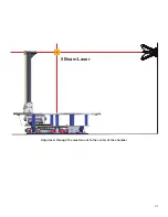
Page 31: ...31 Align laser through the mast mount to the center of the chamber 5 Beam Laser...
Page 34: ...34...
Page 36: ...36...
Page 38: ......


