esatto.house
07
Installation Instructions
PAGE 07
It’s important to carefully read the following installation instructions before beginning the installation of your cooktop.
IMPORTANT!
The connection of this cooktop must be carried out by a suitably qualified and licensed person, in
accordance with the current version of the following:
► AS/NZS 3000: 2007 Wiring Regulations
► 2010 Electricity Safety Regulations
► The installation instructions within this user manual
INSTALLATION INSTRUCTIONS
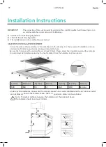
Cut out the work surface according to the sizes shown in the drawing. For the purpose of installation and use,
a minimum of 50mm space shall be preserved around the hole.
Be sure the thickness of the work surface is at least 30mm. Please select heat-resistant work surface material
to avoid larger deformation caused by the heat radiation from the hotplate. As shown below:
L(mm)
W (mm)
H(mm)
D(mm)
A (mm)
B (mm)
X(mm)
520
55
51
560
490
50 mini
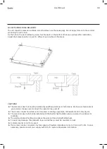
Under any circumstances, make sure the ceramic cooker hob is well ventilated and the air inlet and outlet
are not blocked. Ensure the ceramic cooker hob is in good work state. As shown below:
Note: The safety distance between the hotplate and the cupboard above
the hotplate should be at least 760mm.
590
USER MANUAL
PAGE 06
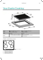
SPECIFICATIONS
MODEL
PRODUCT DIMENSIONS (W×D×H)
CUT-OUT DIMENSIONS (W×D)
IE60T
590mm, 520mm, 55mm
560mm x 490mm
MODEL
BURNERS
OTHER
IE60T
2
x 1.80 kW radiant zones (Ø 190mm)
2 x 1.20 kW radiant zones (Ø 155mm)
Touch control operation
4 x Individual residual heat indicators
Frameless design
CERAMIC COOKTOP SURFACE LAYOUT
YOUR INALTO COOKTOP
1
2
4
3
55
1
2
3
4
1.20kW zone (Ø 155mm)
1.80kW zone (Ø 190mm)
1.20kW zone (Ø 155mm)
1.80kW zone (Ø 190mm)
TOUCH CONTROLS
490


