Edition 080529
-- 21 --
1sC1425
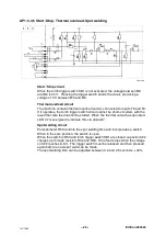
AP1:6 Burnback time
clka1e09
The burn--back time is the time from when wire feed ceases until contactor
KM1 drops off.
During welding, the voltage at pin 13 of IC2 is low. The output of the inverter
at pin 14 is therefore high, turning on transistor Q2 and activating relay RE1.
When the torch trigger switch is released, or when the spot welding time
expires, capacitor C23 charges up via resistors R36, R37 and R38. When the
voltage across C23 reaches 8.8 V, output 14 of IC2 goes low, turning off Q2
and causing relay RE1 to drop off.
AP1:7 Control amplifier and pulse width modulator
The control amplifier compares the set value speed signal with the actual
speed and supplies a control signal to the pulse width modulator. The actual
value speed signal is provided by measuring the motor voltage.
The pulse width modulator controls the frequency and pulse time of current to
the wire feed motor.
Summary of Contents for Origo Mag C171
Page 8: ...Edition 080529 8 1sC1425 Mig C141 ...
Page 9: ...Edition 080529 9 1sC1425 Mig C151 ...
Page 10: ...Edition 080529 10 1sC1425 DESCRIPTION OF OPERATION AP1 Control board clka0e02 ...
Page 12: ...Edition 080529 12 1sC1425 AP1 Mig C141 C151 component positions clka0e03 ...
Page 15: ...Edition 080529 15 1sC1425 Mag C171 ...
Page 16: ...Edition 080529 16 1sC1425 Mag C201 ...
Page 17: ...Edition 080529 17 1sC1425 DESCRIPTION OF OPERATION AP1 Control board clka1e03 ...
Page 18: ...Edition 080529 18 1sC1425 clka1e04 ...
Page 23: ...Edition 080529 23 1sC1425 AP1 Mag C171 C201 component positions clka1e05 ...
Page 26: ...Edition 080529 26 1sC1425 Mag C251 ...
Page 31: ...Edition 080529 clkb0e13 31 1sC1425 AP1 Mag C251 component positions ...
Page 36: ...Edition 080529 36 2sC1425 OrigoTM Mig C151 1 3 2 ...
Page 37: ...Edition 080529 37 2sC1425 OrigoTM Mag C171 C201 C251 1 3 2 Electrical installation ...
Page 43: ... 43 notes NOTES ...
Page 44: ... 44 notes ...


