


ESAB ET 186i AC/DC
Manual 0-5425 A-3 APPENDIX
ET
186i AC/DC
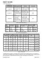
SET-UP GUIDE
Art# A-13120
WAVE BALANCE
ARC FORCE
Pre
Flow
Post
Flow
Initial
Current
Up
Slope
Down
Slope
Crater
Current
Base
Current
Frequency
f
w
Width
High Current
Low
Current
Hot
Start
t1
t2
A
I
z
I
s
I
2
I
e
I
1
MODE
PULSE
PURGE
PROCESS
LIFT TIG
V
SEC
%
Hz
HF TIG
STICK
2T
4T
TRIGGER
BACK
FORWARD
AC FREQUENCY
V
832214_AA
Select
Mode:
or
Select Process:
LIFT TIG, HF TIG,
or STICK
Adjust
Parameters
STICK
2T Mode (AC or DC)
4T Mode (AC or DC)
(AC or DC)
Pre Flow
Hot Start (HF TIG Only)
Weld Current
Down Slope
Post Flow
Wave Balance (AC TIG Only)
AC Frequency (AC TIG Only)
Pre Flow
Hot Start (HF TIG Only)
Initial Current
Up Slope
Weld Current
Down Slope
Crater Current
Post Flow
Wave Balance (AC TIG Only)
AC Frequency (AC TIG Only)
Hot Start
Weld Current
Arc Force
1
2
3
DC
AC
LIFT TIG & HF TIG
a
b
1
2
Weld Current (Range)
-
100-160A
-
Arc Force
-
-
-
Polarity Selection
Weld Current (Range)
30-60A
55-95A
80-140A
Arc Force
-
-
-
Polarity Selection
STICK
3/32"
(2.4 mm)
1/8"
(3.2 mm)
5/32"
(4.0 mm)
Weld Current (Range)
50-75A
70-110A
80-145A
Arc Force
-
-
-
Polarity Selection
Weld Current (Range)
70-95A
100-135A
145-170A
Arc Force
-
-
-
Polarity Selection
Weld Current (Range)
70-95A
100-145A
135-170A
Arc Force
-
-
-
Polarity Selection
Weld Current (Range)
70-110A
90-160A
130-170A
Arc Force
-
-
-
Polarity Selection
E6011
E6013
E7014
E7018
STICK
E308L-16
E316L-16
E7024
Note:
STICK set-up guide parameters may vary depending upon welding position, joint design.
SELECT
PROCESS
MODE
SELECTION
ELECTRODE
DIAMETER
DC Reverse Polarity (Positive)
DC Reverse Polarity (Positive)
DC Reverse Polarity (Positive)
DC Reverse Polarity (Positive)
DC Reverse Polarity (Positive)
DC Reverse Polarity (Positive)
3
3
3
3
3
3
ELECTRODE
SELECTION
DC(+)
DC(+)
SELECT
PROCESS
MODE
SELECTION
MATERIAL
SELECTION
BASE
METAL SIZE
HIGH
CURRENT
WIDTH
FREQUENCY
LOW
CURRENT
16 ga. (1.6 mm)
120A
60%
100 Hz Pulse
55A
1/8" (3.2 mm)
170A
60%
1 Hz Pulse
60A
16 ga. (1.6 mm)
65A
50%
1 Hz Pulse
30A
1/8" (3.2 mm)
125A
65%
1 Hz Pulse
50A
3/16" (4.7 mm)
195A
60%
1 Hz Pulse
75A
16 ga. (1.6 mm)
85A
60%
1 Hz Pulse
40A
1/8" (3.2 mm)
150A
60%
1 Hz Pulse
50A
a
b
1
2
*
- If Required
Aluminum
Mild Steel
Stainless
Steel
4, 5, 6
15 cfh (7 l/m)
4, 5, 6
15 cfh (7 l/m)
6, 7
17 cfh (8 l/m)
6, 7
17 cfh (8 l/m)
7, 8
17 cfh (8 l/m)
7, 8
17 cfh (8 l/m)
Pulse
Pulse
AC
16 ga. (1.6 mm)
Butt
1/16" (1.6 mm)
50A
-
5 sec.
16 ga. (1.6 mm)
Fillet
1/16" (1.6 mm)
60A
-
6 sec.
1/8" (3.2 mm)
Butt
3/32" (2.4 mm)
125A
-
11 sec.
1/8" (3.2 mm)
Fillet
3/32" (2.4 mm)
125A
-
13 sec.
3/16" (4.7 mm)
Butt
1/8" (3.2 mm)
170A
-
13 sec.
3/16" (4.7 mm)
Fillet
1/8" (3.2 mm)
200A
-
13 sec.
Mild
Steel
LIFT TIG
/HF TIG
LIFT TIG
/HF TIG
Note:
Butt or Fillet Joint types can be used in Pulse mode. Set-up guide parameters may vary depending upon welding position.
SELECT
PROCESS
MODE
SELECTION
MATERIAL
SELECTION
BASE
METAL SIZE
JOINT
TYPE
TUNGSTEN /
FILLER ROD SIZE*
WELD
CURRENT
AC
FREQUENCY
POST
FLOW
16 ga. (1.6 mm)
Butt
1/16" (1.6 mm)
65A
150 Hz
5 sec.
16 ga. (1.6 mm)
Fillet
1/16" (1.6 mm)
85A
150 Hz
6 sec.
1/8" (3.2 mm)
Butt
3/32" (2.4 mm)
135A
150 Hz
11 sec.
1/8" (3.2 mm)
Fillet
3/32" (2.4 mm)
150A
150 Hz
13 sec.
3/16" (4.7 mm)
Butt
1/8" (3.2 mm)
160A
100 Hz
13 sec.
3/16" (4.7 mm)
Fillet
1/8" (3.2 mm)
170A
80 Hz
13 sec.
1/4" (6.4 mm)
Butt
1/8" (3.2 mm)
200A
80 Hz
13 sec.
1/4" (6.4 mm)
Fillet
1/8" (3.2 mm)
200A
80 Hz
13 sec.
16 ga. (1.6 mm)
Butt
1/16" (1.6 mm)
50A
-
5 sec.
16 ga. (1.6 mm)
Fillet
1/16" (1.6 mm)
60A
-
6 sec.
1/8" (3.2 mm)
Butt
3/32" (2.4 mm)
110A
-
11 sec.
1/8" (3.2 mm)
Fillet
3/32" (2.4 mm)
150A
-
13 sec.
3/16" (4.7 mm)
Butt
1/8" (3.2 mm)
170A
-
13 sec.
3/16" (4.7 mm)
Fillet
1/8" (3.2 mm)
170A
-
13 sec.
1/4" (6.4 mm)
Butt
1/8" (3.2 mm)
175A
-
13 sec.
1/4" (6.4 mm)
Fillet
1/8" (3.2 mm)
180A
-
13 sec.
Aluminum
HF TIG
LIFT TIG
/HF TIG
Stainless
Steel
a
b
c
d
1
2
DC (-)
DC(-)
AC
SELECT TIG
CUP SIZE
SELECT
GAS FLOW
4, 5, 6
15 cfh (7 l/m)
4, 5, 6
15 cfh (7 l/m)
6, 7
17 cfh (8 l/m)
6, 7
17 cfh (8 l/m)
7, 8
17 cfh (8 l/m)
7, 8
17 cfh (8 l/m)
7, 8
17 cfh (8 l/m)
7, 8
17 cfh (8 l/m)
4, 5, 6
15 cfh (7 l/m)
4, 5, 6
15 cfh (7 l/m)
6, 7
17 cfh (8 l/m)
6, 7
17 cfh (8 l/m)
7, 8
17 cfh (8 l/m)
7, 8
17 cfh (8 l/m)
7, 8
17 cfh (8 l/m)
7, 8
17 cfh (8 l/m)
3
3
LIFT TIG / HF TIG Notes
Gas is 100% Pure Argon.
Wave balance is 30%
(AC Mode Only)
Note:
LIFT TIG / HF TIG set-up guide parameters may vary depending upon welding position and joint design.
Pulse Notes
Wave
Balance
is 30%
(AC Mode
Only)
DC(-)
LIFT TIG / HF TIG
SET-UP GUIDE
PULSE
SET-UP GUIDE
PANEL
SET-UP GUIDE
STICK
SET-UP GUIDE
This set-up information
is intended to act as a
guide only.
Please refer to operating
manual for further
information.
PART # :
832214
DESCRIPTION :
Label, ESAB ET 186i AC/DC Set-Up Guide (USA)
SCALE :
1:1
SIZE :
375 mm x 203 mm x R 6.35
DRAWN :
ART
DATE :
10/16/15
COLORS :
MATERIALS:
Base:
2 mil thick white substrate with 3 mil clear overlaminate
Overlaminate:
.see above
Adhesive:
3M Grade 468
NOTES:
Cutout (1) Indicated by color shown :
Yellow - PMS 012C
Grey - Cool Gray 10C
White
Black - PMS Black or RAL 9005 equivalent
Grey - Cool Gray 2C
DATE
BY
REVISIONS
REV
AA
ART
For Production Use. VCN-01616
05/31/16
Information proprietary to ESAB
esab.com
ESAB Welding & Cutting Products
Denton, TX U.S.A.


