


ESAB ET 186i AC/DC
BASIC WELDING GUIDE 4-4 Manual 0-5425
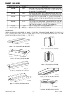
Striking the Arc
Practice this on a piece of scrap plate before going on to more exacting work. You may at first experience difficulty due to the tip of
the electrode "sticking" to the work piece. This is caused by making too heavy a contact with the work and failing to withdraw the
electrode quickly enough. A low amperage will accentuate it. This freezing-on of the tip may be overcome by scratching the elec-
trode along the plate surface in the same way as a match is struck. As soon as the arc is established, maintain a 1/16" (1.6mm) to
1/8" (3.2mm) gap between the burning electrode end and the parent metal. Draw the electrode slowly along as it melts down.
Another difficulty you may meet is the tendency, after the arc is struck, to withdraw the electrode so far that the arc is broken
again. A little practice will soon remedy both of these faults.
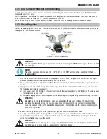
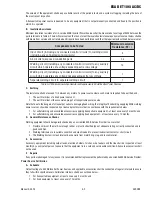
Art # A-07696_AB
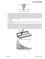
20°
1.6 mm (1/16”)
Figure 4-10: Striking an Arc
Arc Length
The securing of an arc length necessary to produce a neat weld soon becomes almost automatic. You will find that a long arc
produces more heat. A very long arc produces a crackling or spluttering noise and the weld metal comes across in large, irregular
blobs. The weld bead is flattened and spatter increases. A short arc is essential if a high quality weld is to be obtained although if it
is too short there is the danger of it being blanketed by slag and the electrode tip being solidified in. If this should happen, give the
electrode a quick twist back over the weld to detach it.
Rate of Travel
After the arc is struck, your next concern is to maintain it, and this requires moving the electrode tip towards the molten pool at the
same rate as it is melting away. At the same time, the electrode has to move along the plate to form a bead. The electrode is di-
rected at the weld pool at about 20º from the vertical. The rate of travel has to be adjusted so that a well-formed bead is produced.
If the travel is too fast, the bead will be narrow and strung out and may even be broken up into individual globules. If the travel is
too slow, the weld metal piles up and the bead will be too large.
Making Welded Joints
Having attained some skill in the handling of an electrode, you will be ready to go on to make up welded joints.
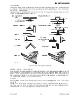
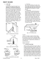
A. Butt Welds
Set up two plates with their edges parallel, as shown in Figure 4-11, allowing 1/16" (1.6mm) to 3/32" (2.4mm)gap between
them and tack weld at both ends. This is to prevent contraction stresses from the cooling weld metal pulling the plates out of
alignment. Plates thicker than 1/4" (6.0mm) should have their mating edges bevelled to form a 70º to 90º included angle. This
allows full penetration of the weld metal to the root.
Do not weave the electrode, but maintain a steady rate of travel along the joint sufficient to produce a well-formed bead. At first
you may notice a tendency for undercut to form, but keeping the arc length short, the angle of the electrode at about 20º from
vertical, and the rate of travel not too fast, will help eliminate this. The electrode needs to be moved along fast enough to prevent
the slag pool from getting ahead of the arc. To complete the joint in thin plate, turn the job over, clean the slag out of the back
and deposit a similar weld.
Art # A-07697_AB
Tack Weld
20°-30°
Electrode
Tack Weld
Figure 4-11: Butt Weld


